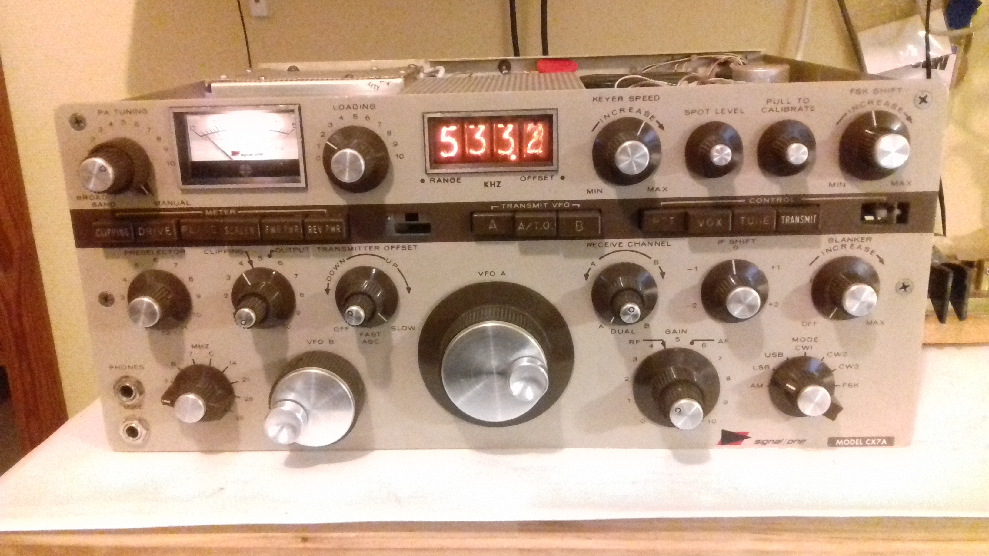
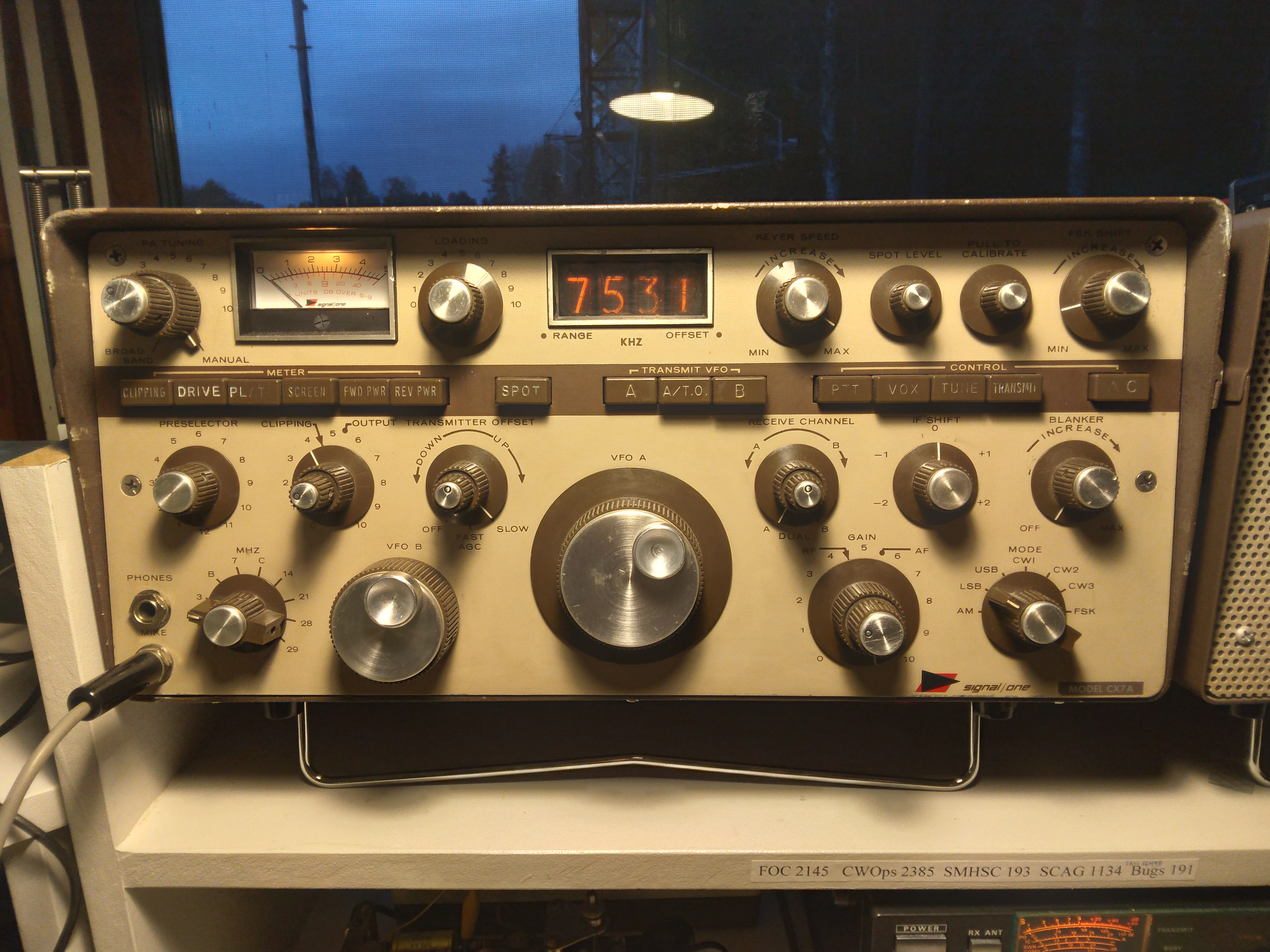
Trying to bring a classic CX7A flagship back to life
This is the story of an attempt to restore a badly bruised and battered CX7A that my friend bought at a fleamarket some time ago. The radio came from a SK estate and the brown cabinet was nowhere to be found.. It's history is not fully known but the call SM5NAB is written with a pencil on the side of the chassie.
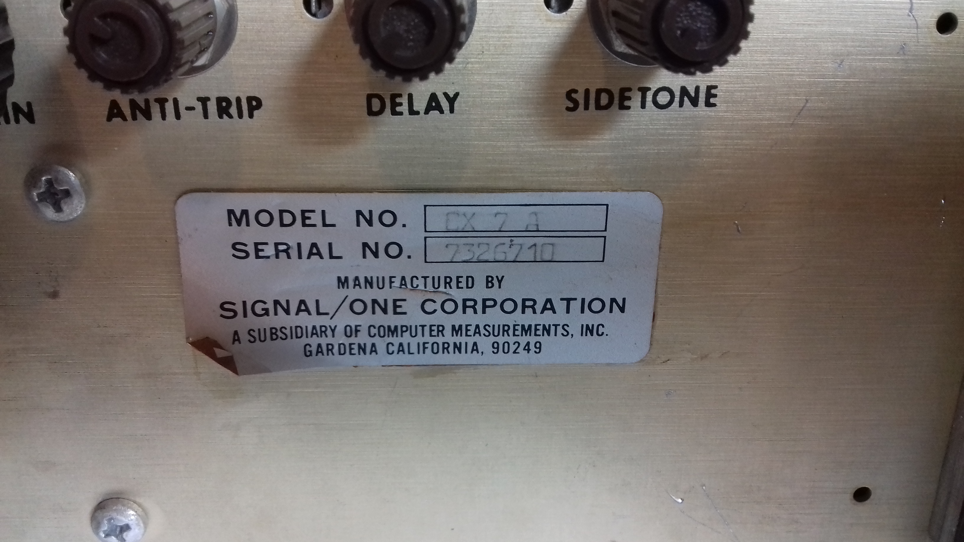
The serial number:
The radio was dead when trying to start it up. The AC power on button is missing and behind it was a mess of wires and a capacitor. Apparently someone who had worked on it did not realize that what looked like a capacitor was actually an NTC resistor and therefore replaced it with a 10 nF ceramic capacitor.
To make a long story short, I eventually got the remains of the AC button sorted, replaced the capacitor for a NTC resistor and the set came to life... well, some sort of dead life..
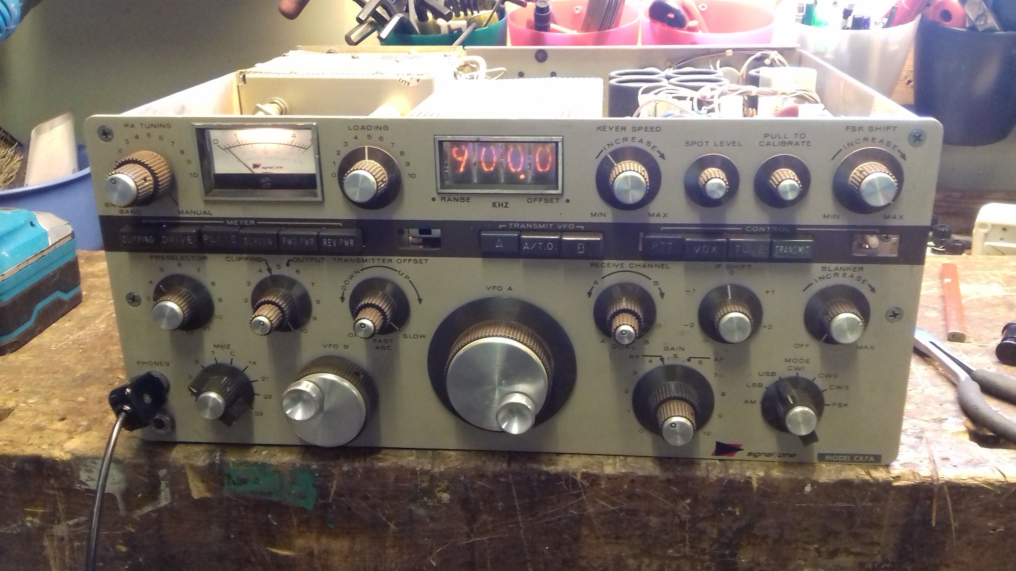
The display shows 900.0 at all times, the VFO's don't work and there is no sound at all coming from the radio. It does not switch to transmit.
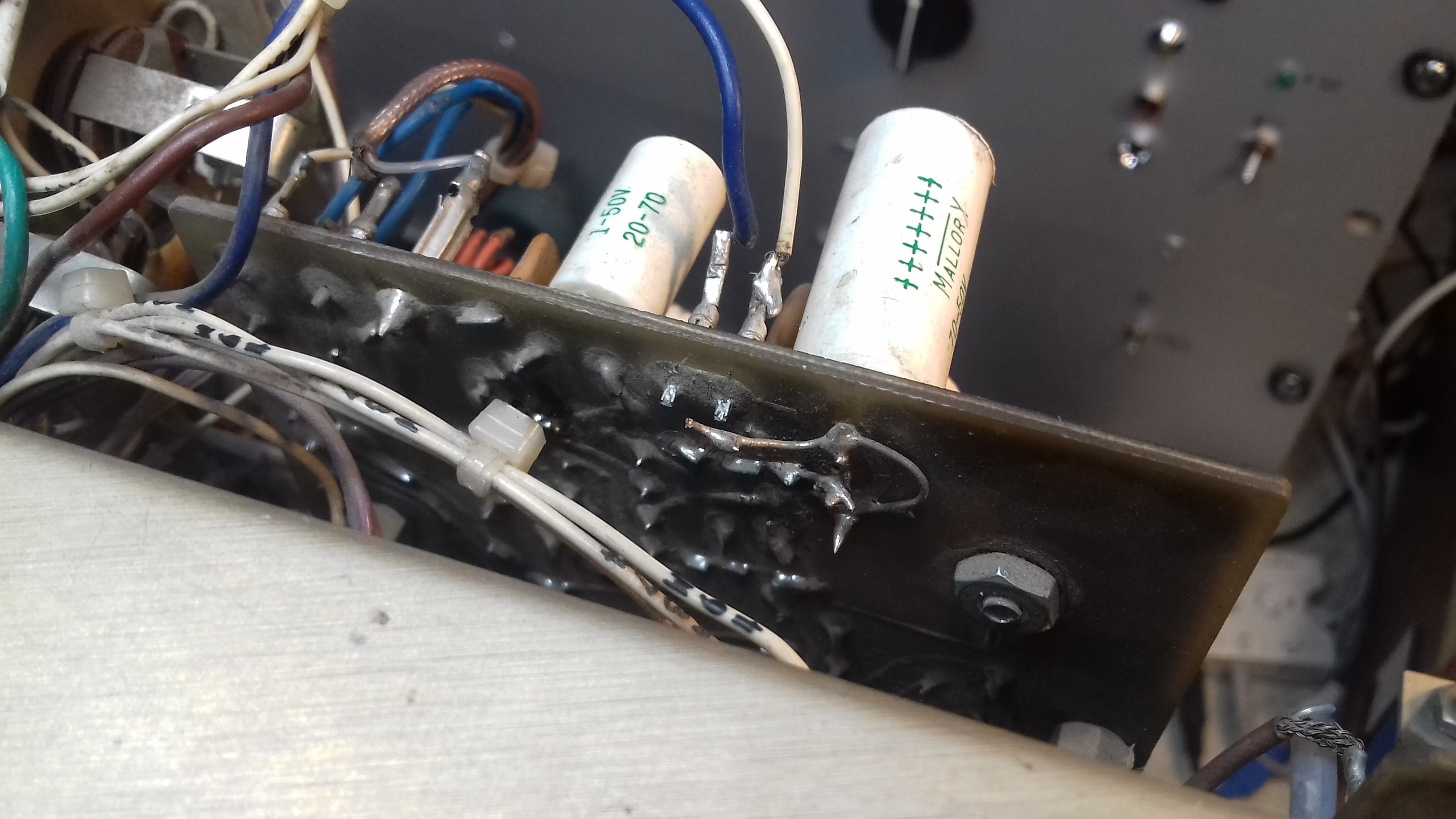
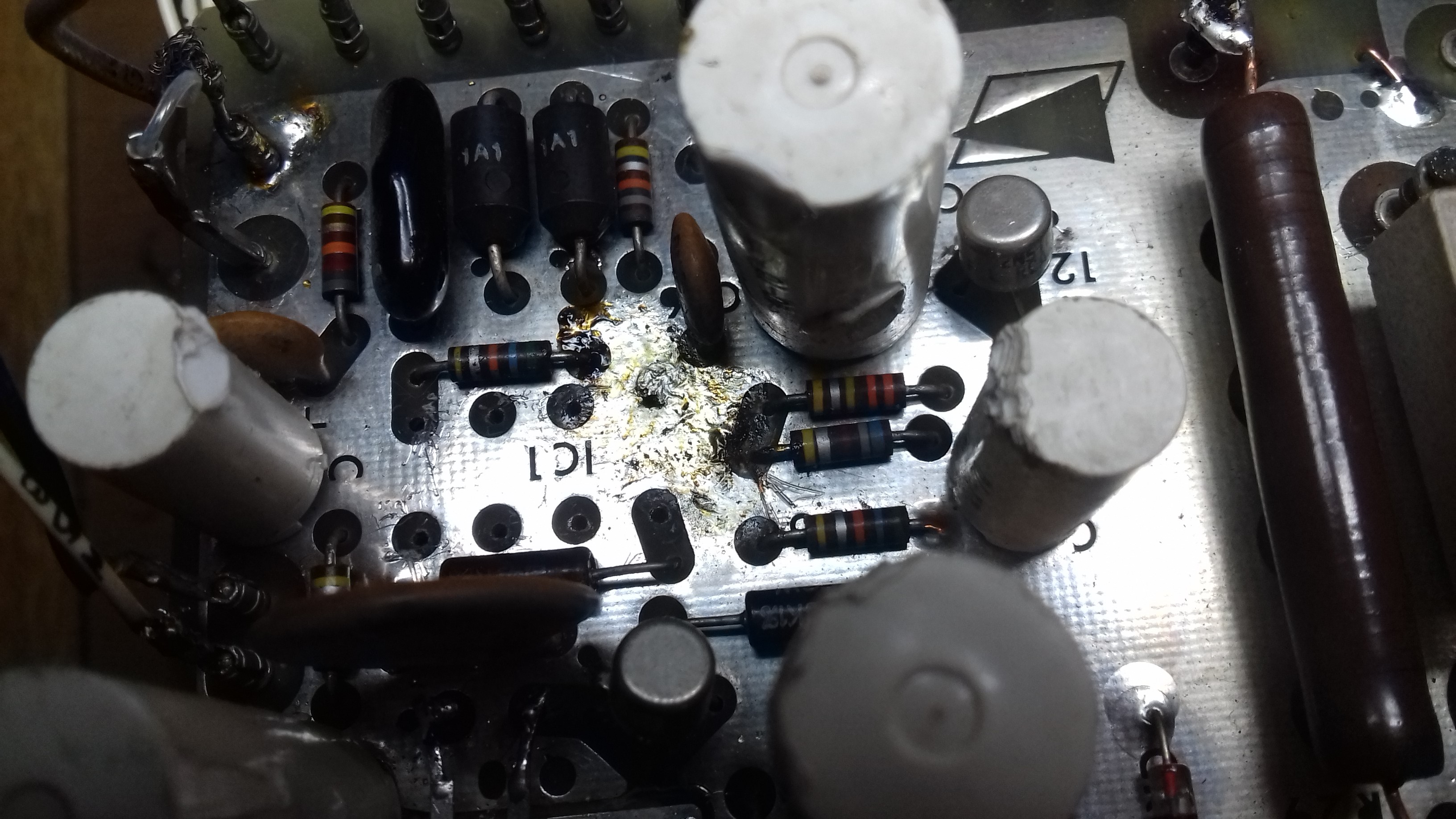
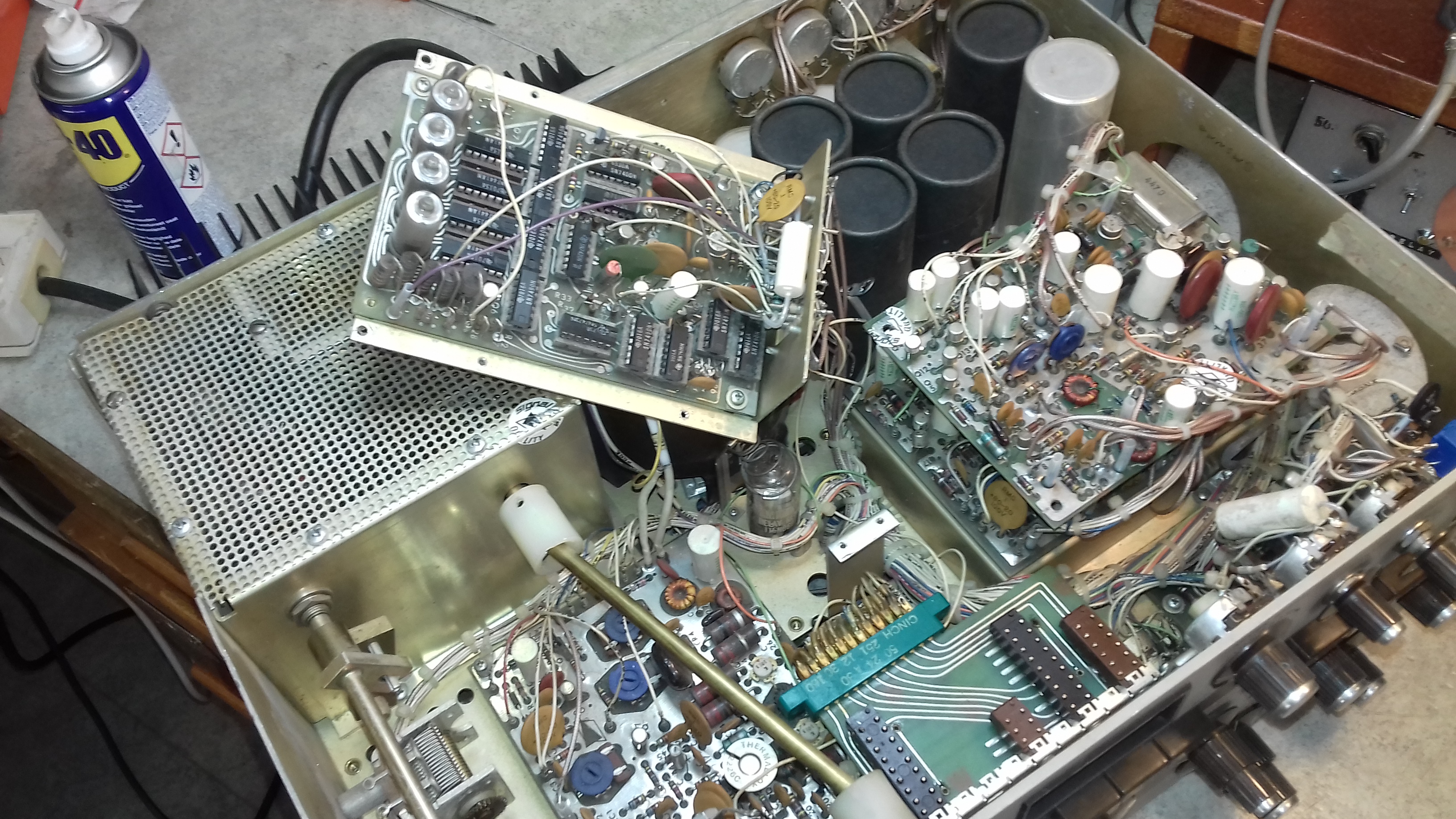
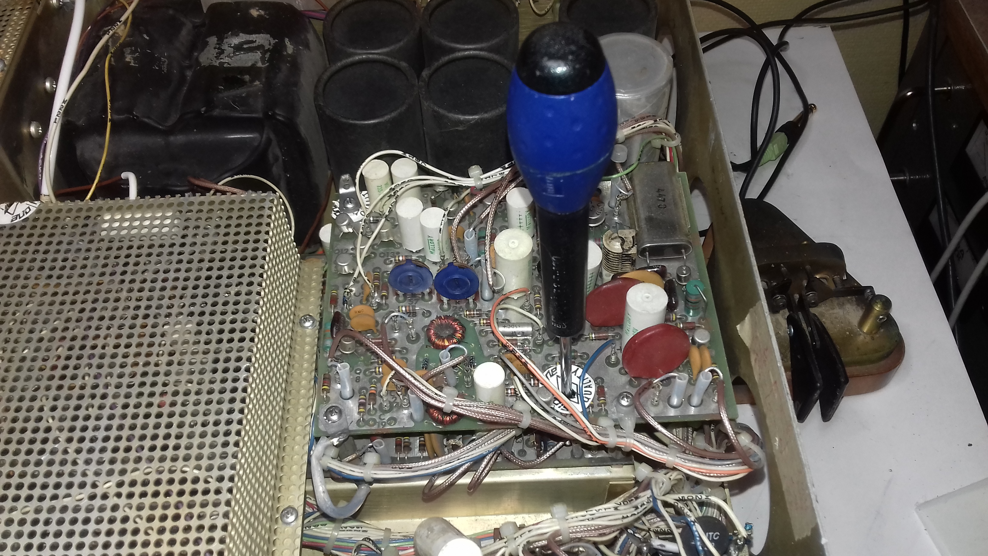
I started looking at the power supply board and noticed that the audio chip IC1 has been badly bruised and there is a big blob of solder around it. Capacitors surrounding the audio chip are burned by someone not used to handling a soldering iron.
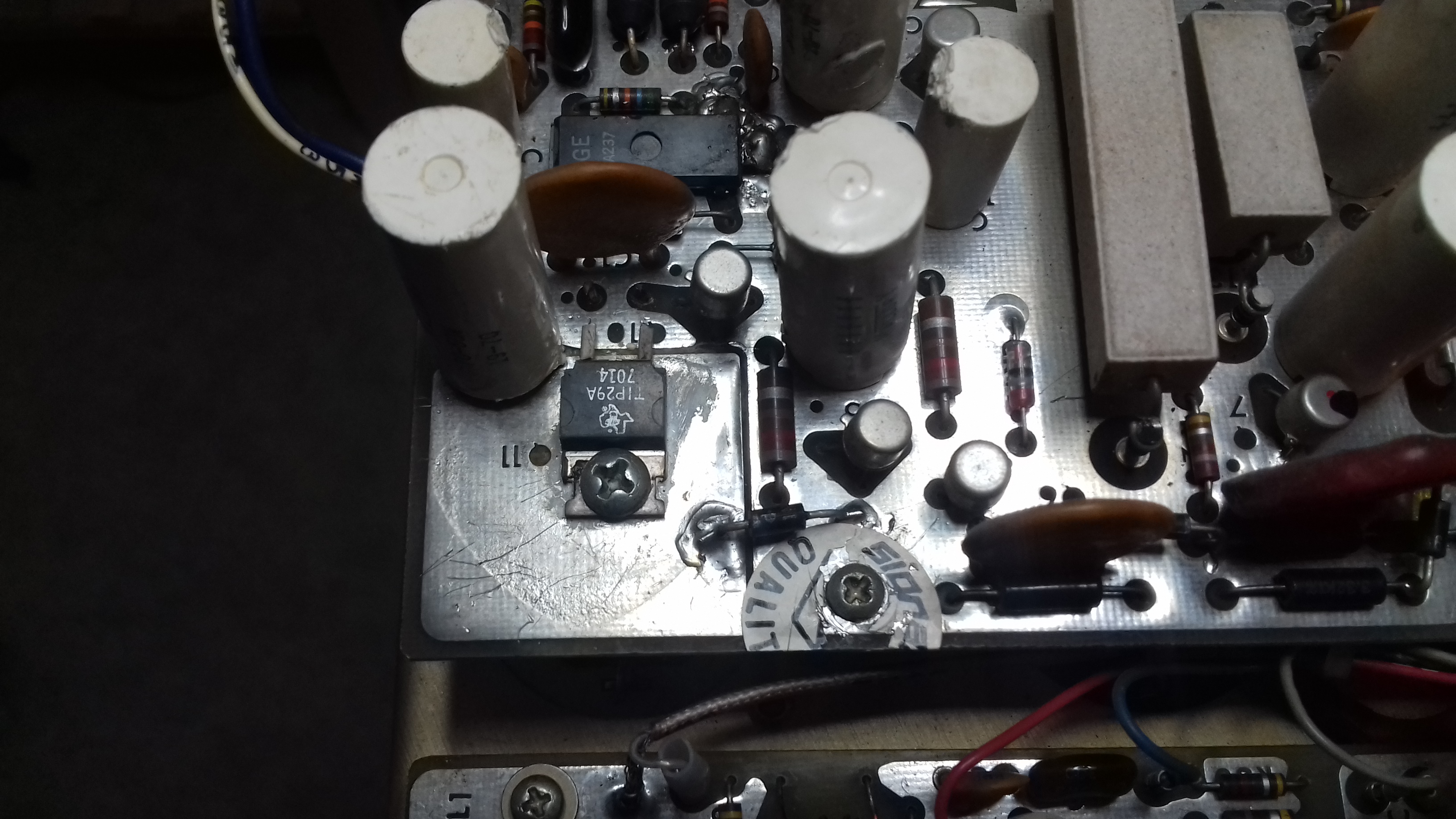
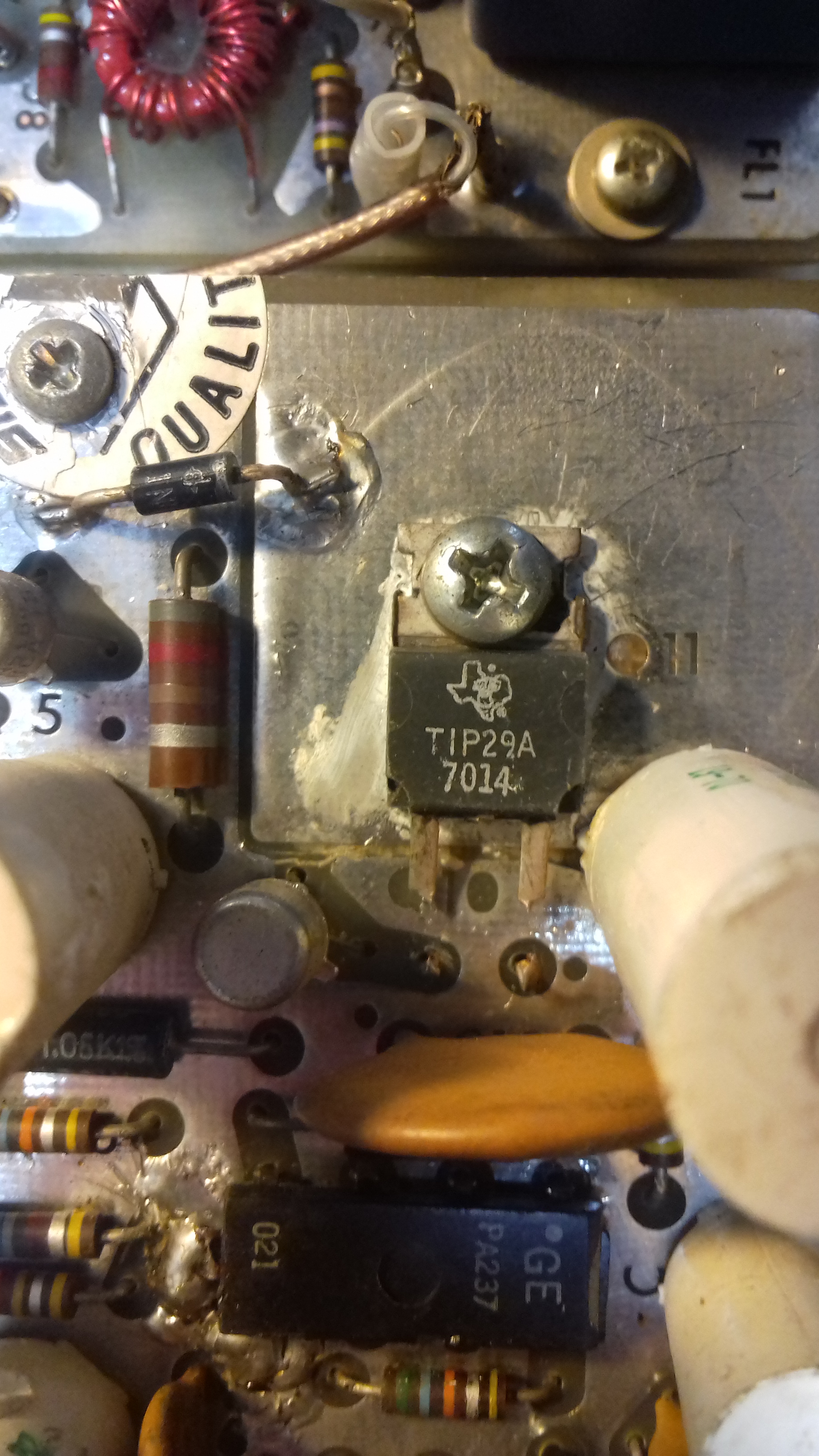
There are also burned traces on the PC-board adjacent the the audio chip. Traces are replaced with wire. Not a pretty sight. It is obvious that IC1 had shorted and that in turn caused burned traces on the PC board.
Troubleshooting reveals that the power supply board has a lot of issues, not only the audio chip is dead, a lot of transistors and diodes are also dead. Vital voltages are missing.
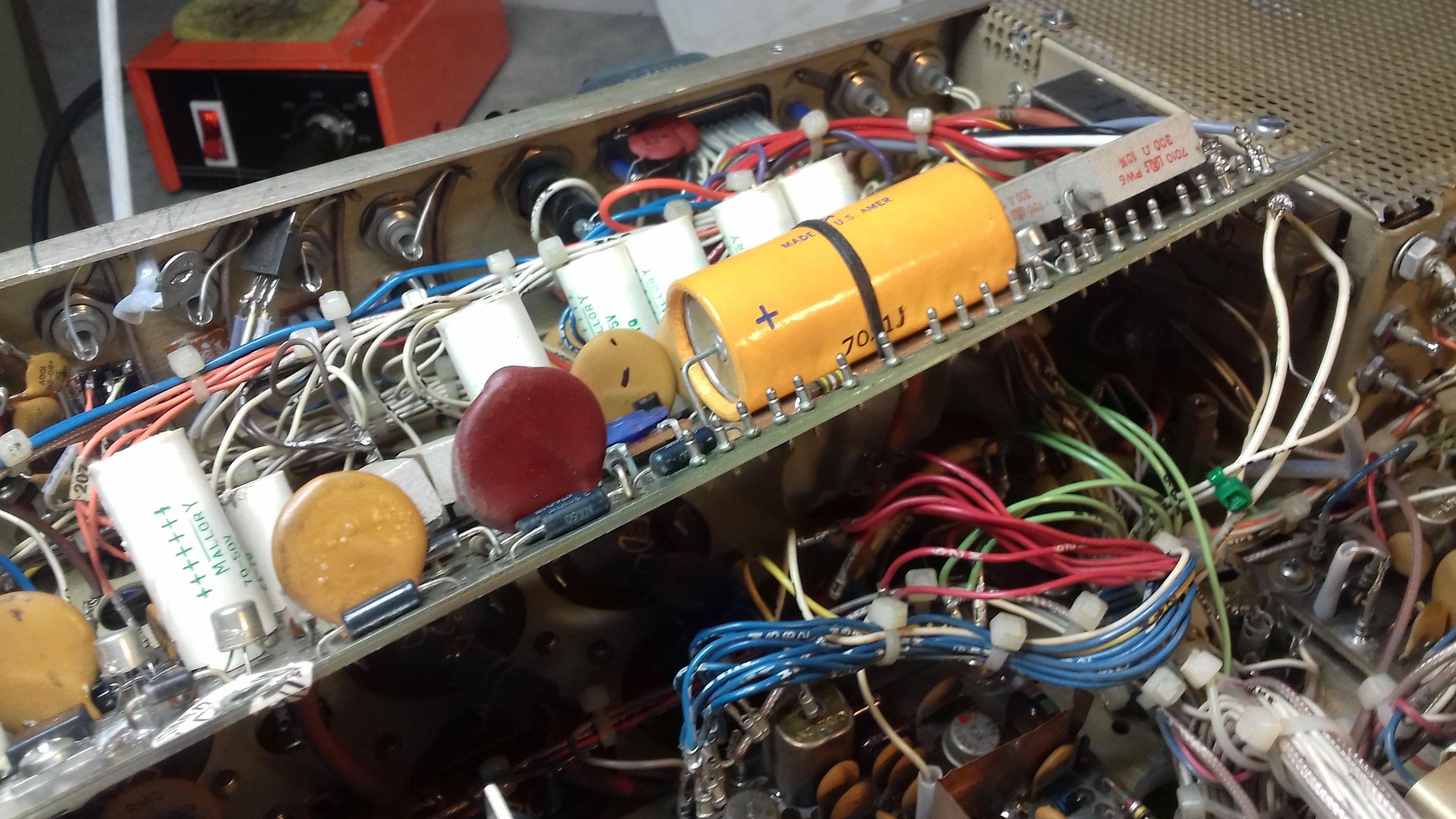
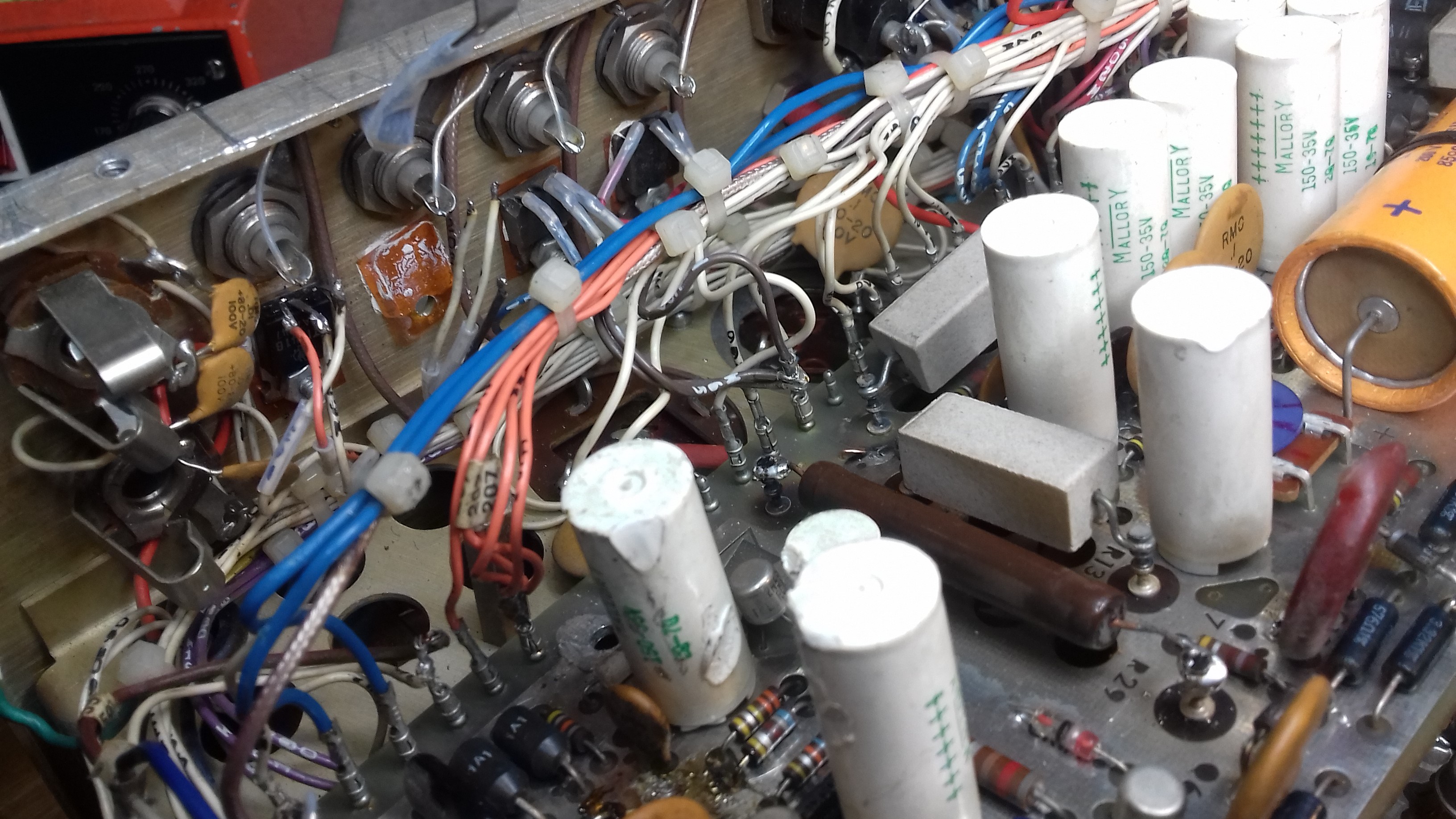
So I decide to start rebuilding the board and restore all voltages to specifications in the service manual. This includes modifying the power supply as described by Bob Sullivan W0YVA/4 in an article in CQ Magazine January 1977 using solid state regulators for the low voltages. The pictures below show some of that work. I also decided to get rid of the audio chip completely and go for a new solution with a more modern chip.
All voltages are now restored, including the high voltage for the PA tube.
Audio chip IC1 removed and some short circuits removed. and cleaned up
Here we can see some white patch wires in place after removing transistors on the board in accordance with Bob's article. Suspect solderings are resoldered.
Transistors replaced with modern 78XX/79XX regulators
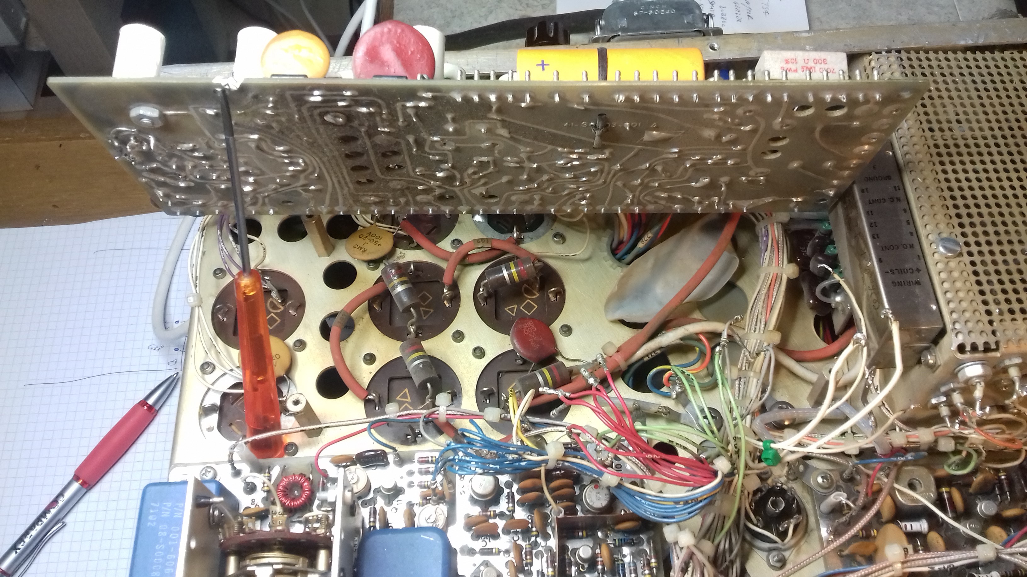
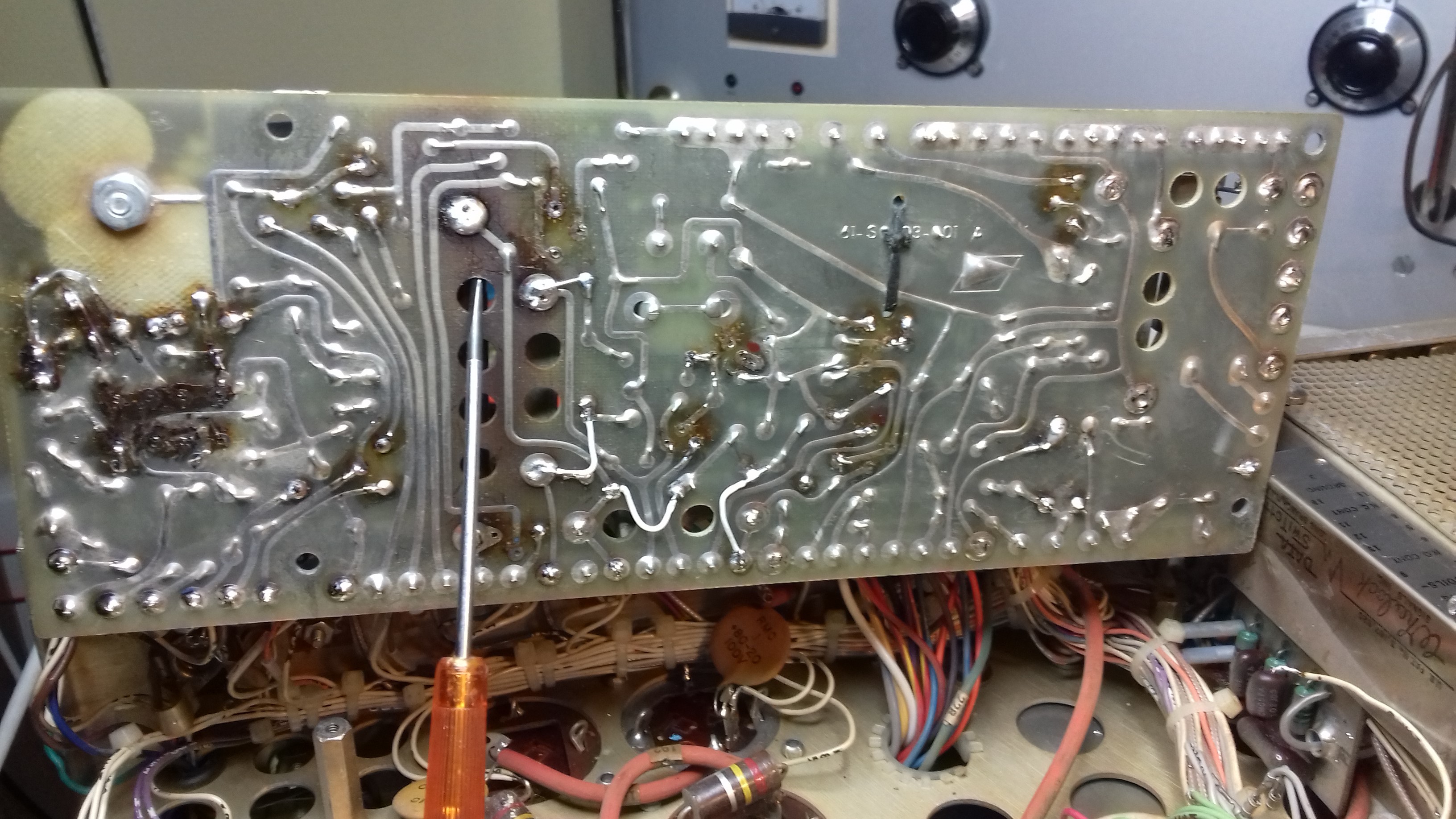
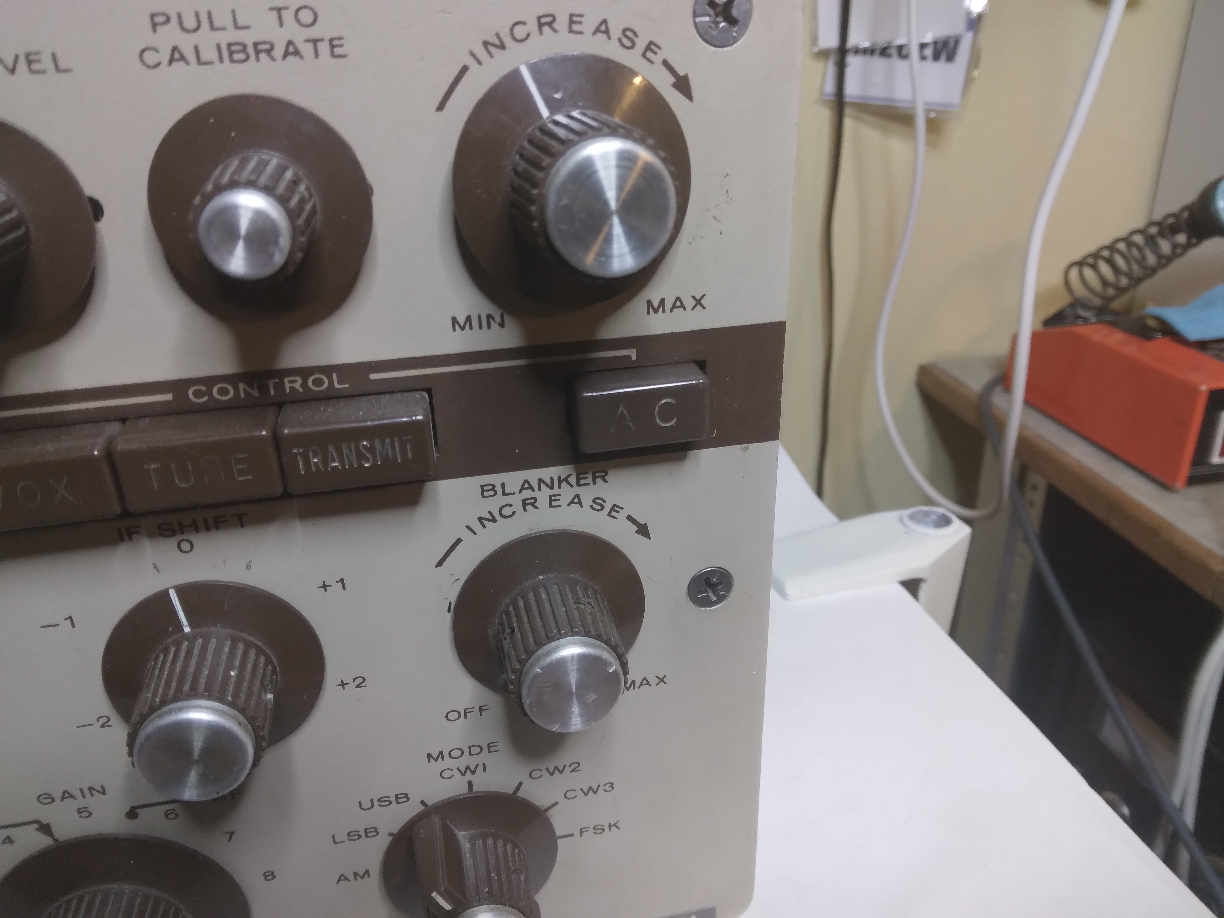
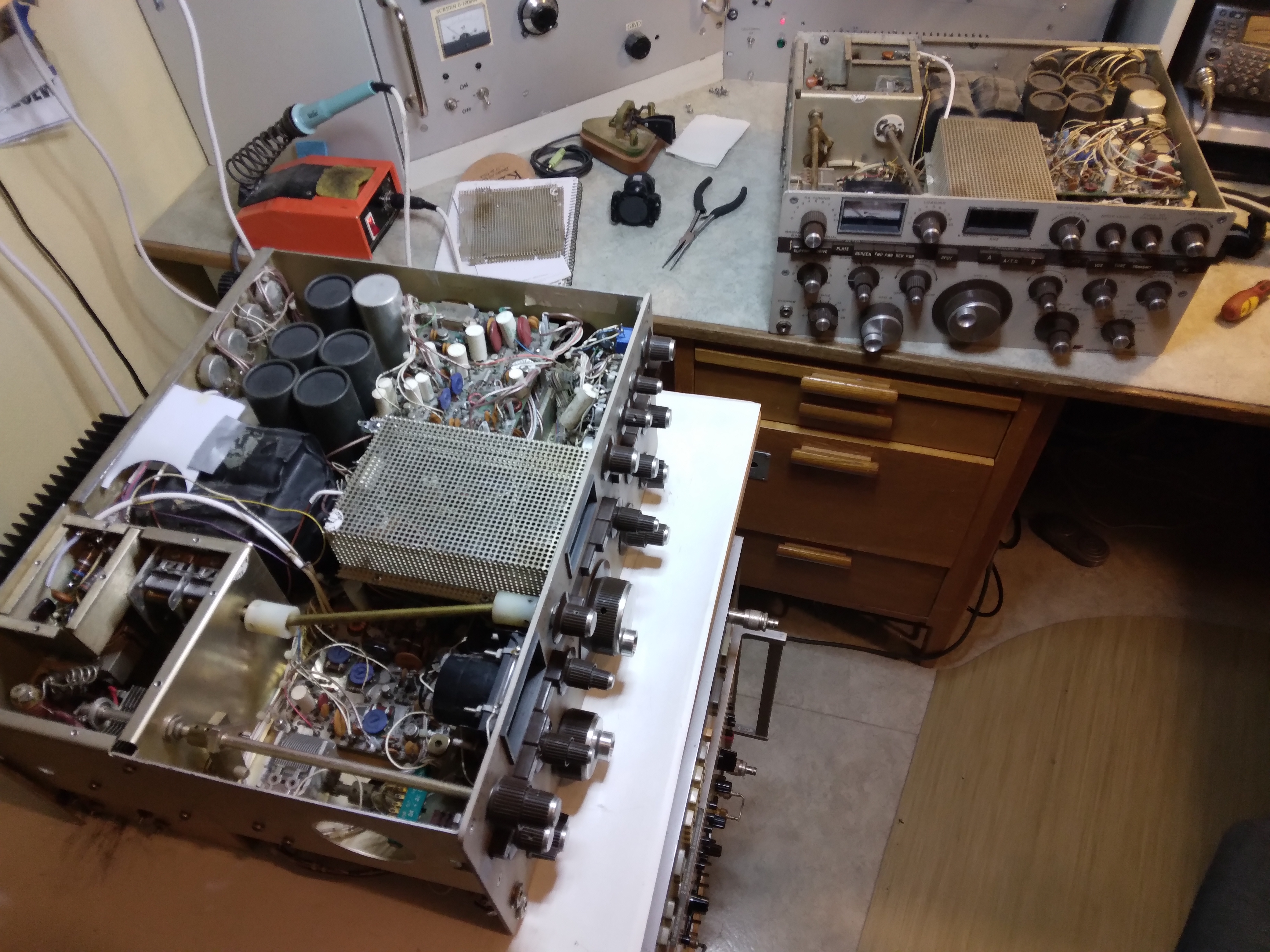
After getting all the voltages restored and measured I decided to take a closer look at the boards just to make sure that there were no more "fixes" like the ones on the power supply board. I also wanted to clean the button switches and treat them with some lubricant so they wouldn't stick. As noted in the first picture, the "SPOT" button is totally missing on this set. And it's not just the button that is missing, it's also the interior of the switch is gone.
While having the boards available for inspection with a magnifying glass I also re-soldered what appeared to be bad solderings.
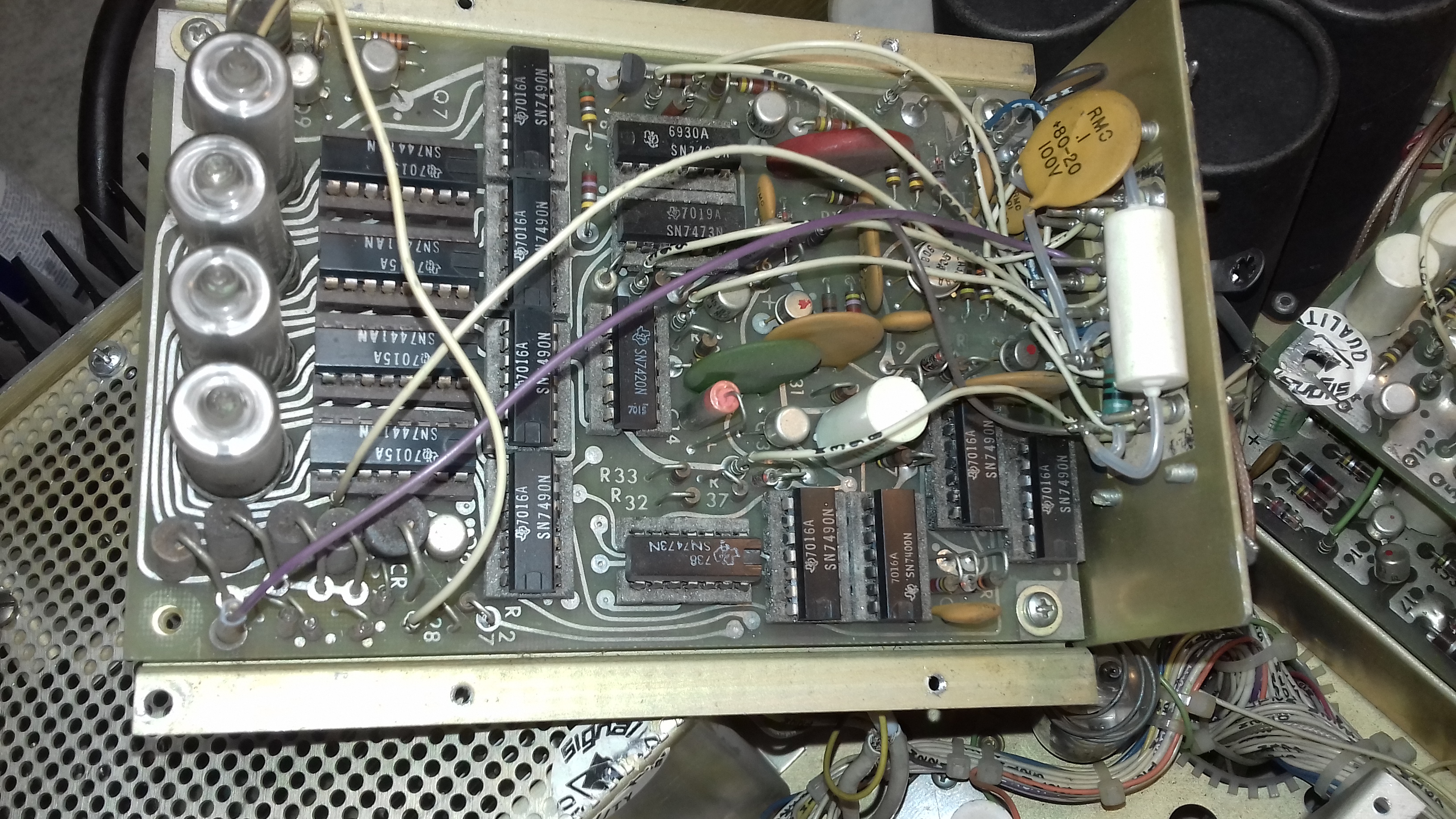
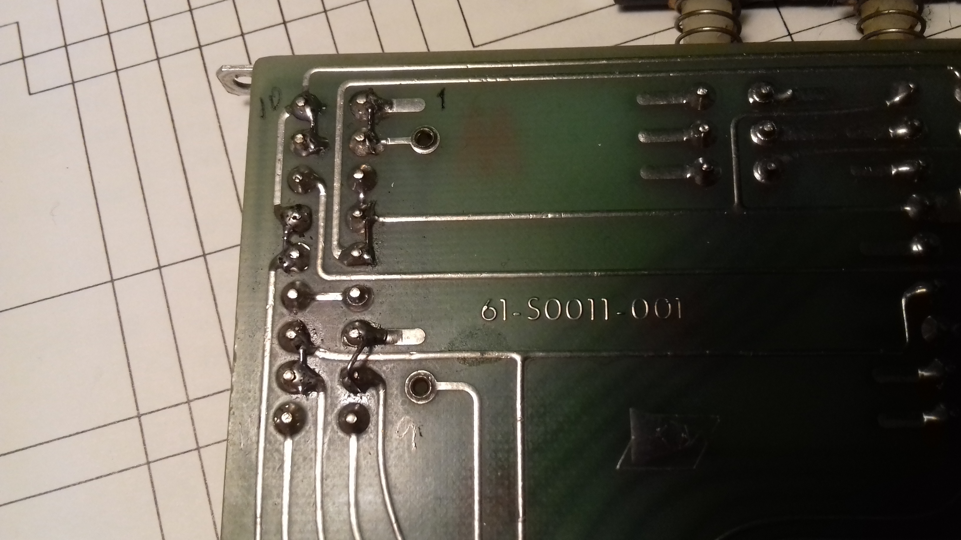
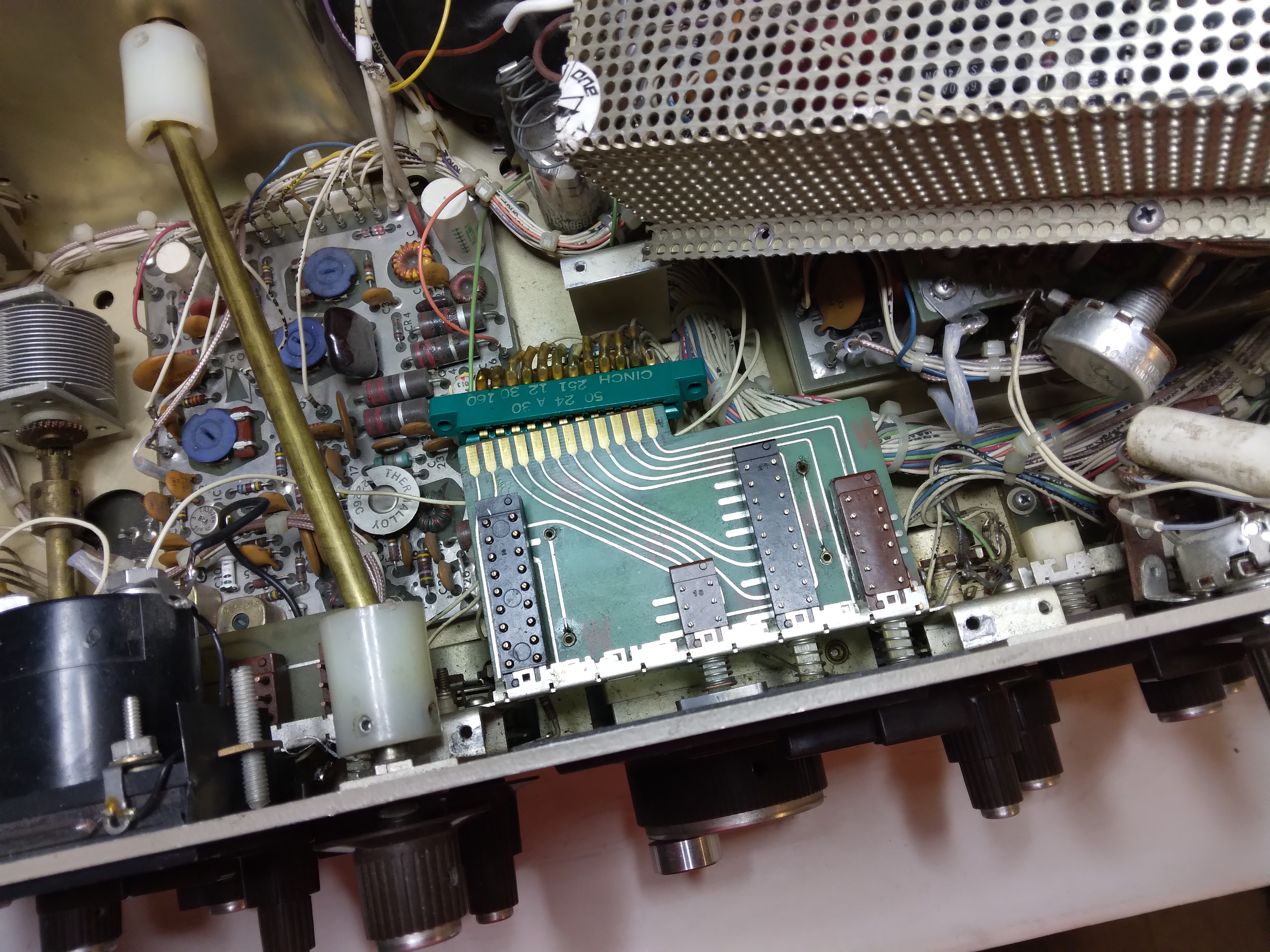
The counter board in this CX7A have sockets for the IC's. In my CX7 (s/n 0019) the chips are soldered to the board, no sockets. The sockes are indeed a much better solution :-)
Below is a picture of the central push button section where it is obvious that the "SPOT" button and all of the interior of the switch is gone.
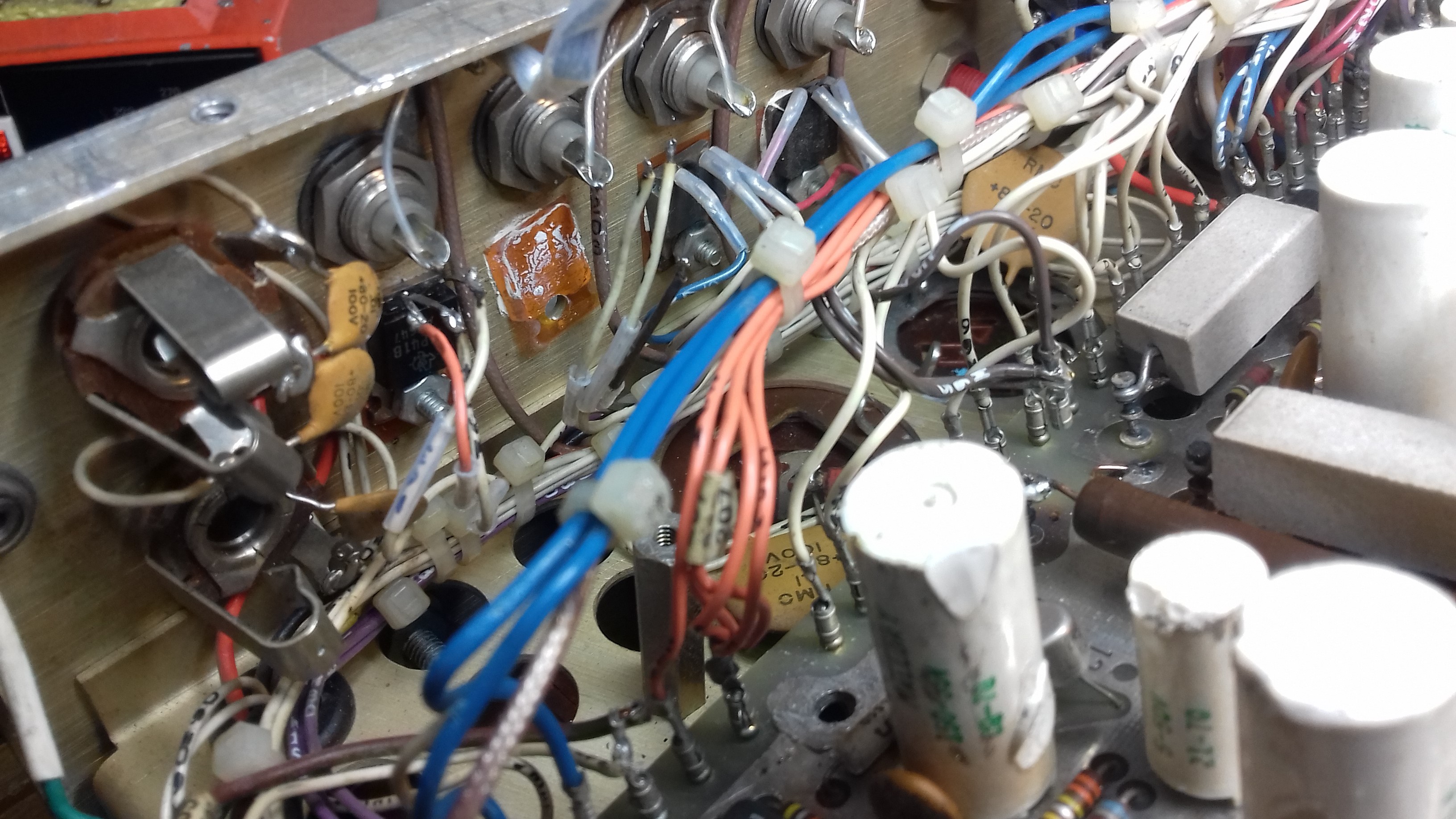
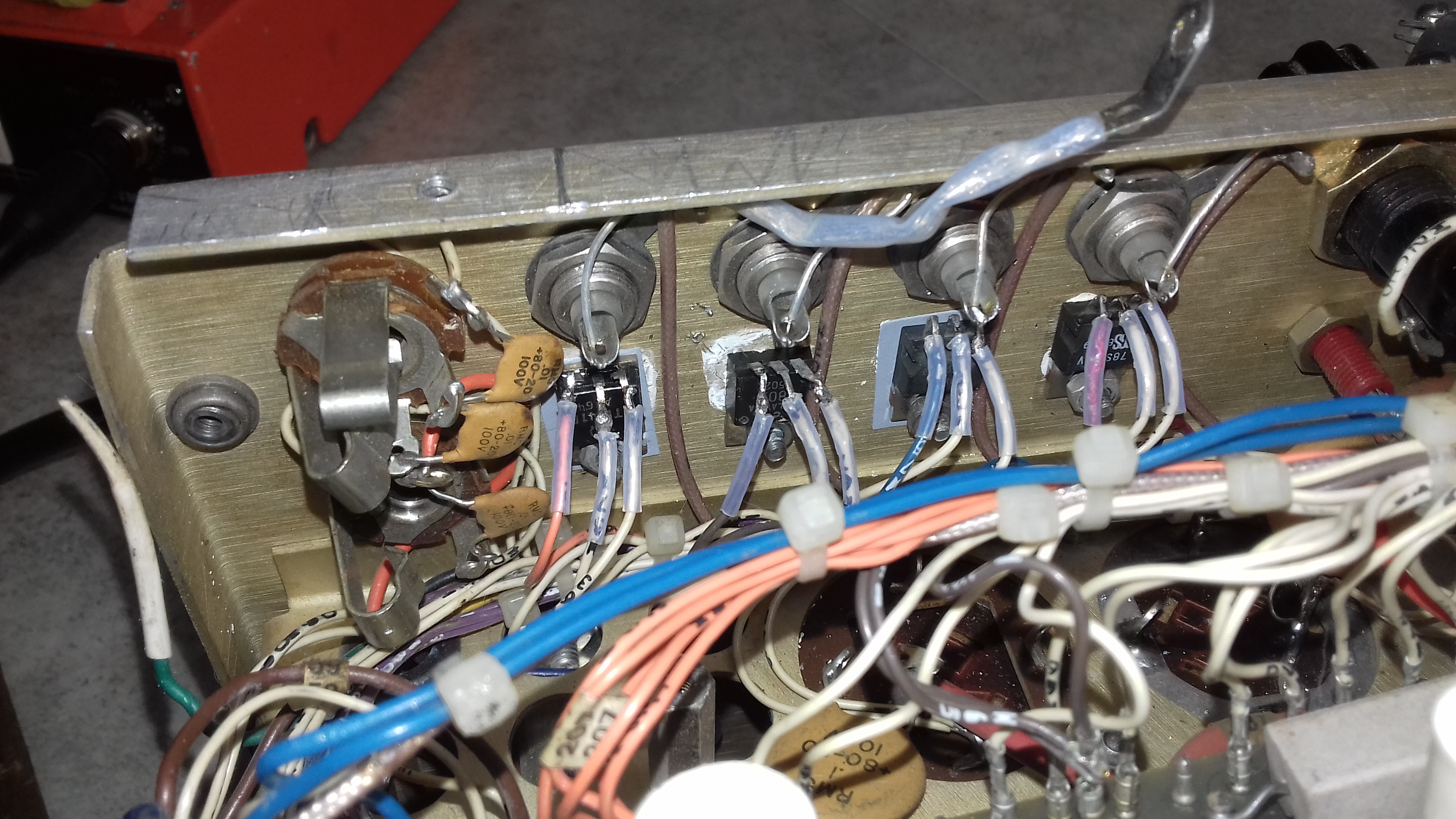
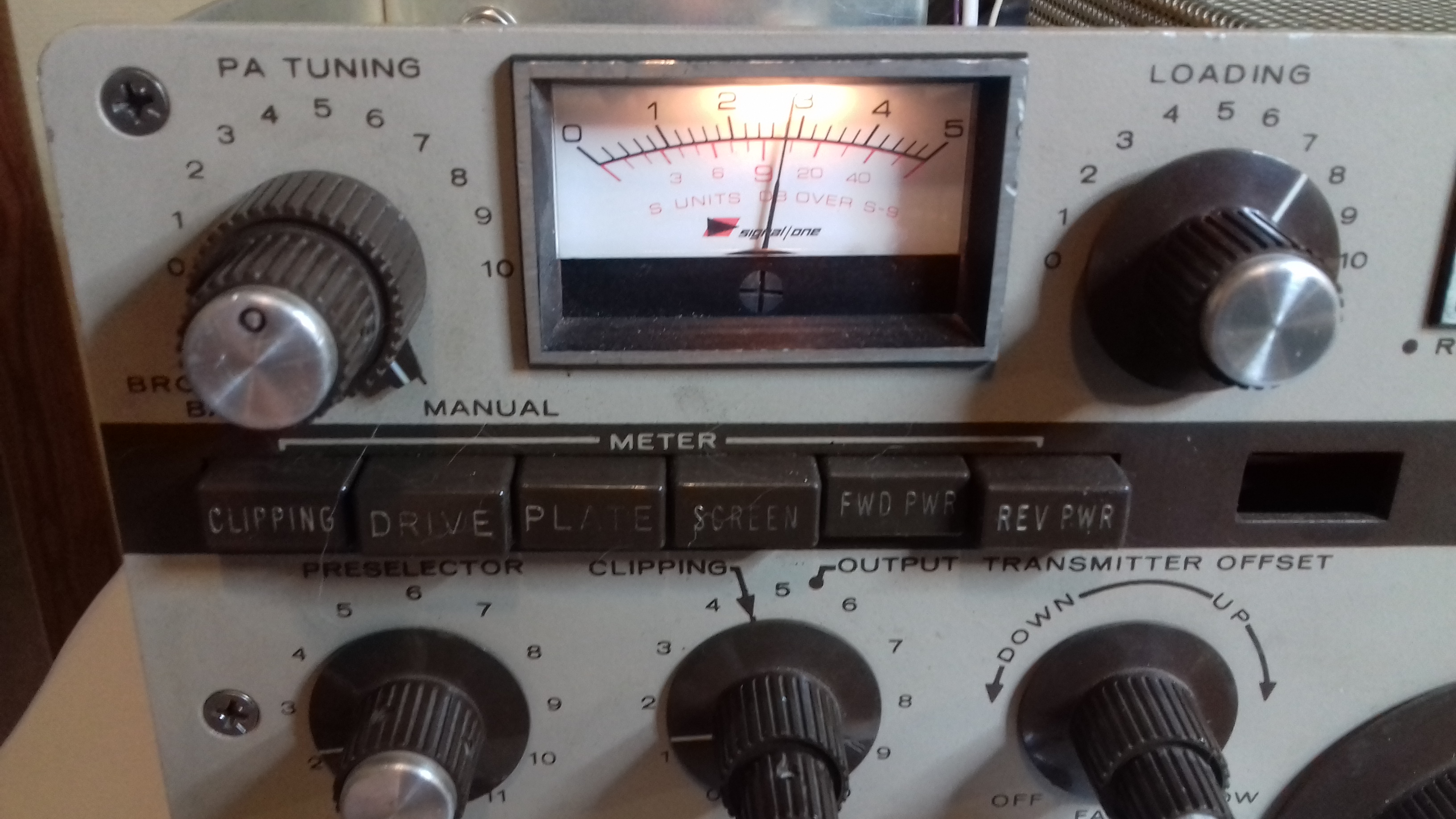
Another issue I noticed was that the wires to the meter were jammed and grounded to the chassie behind a replaced "CLIPPING/OUTPUT" potentiometer. Fixing that made the meter work again as shown when I backed the RF Gain off.
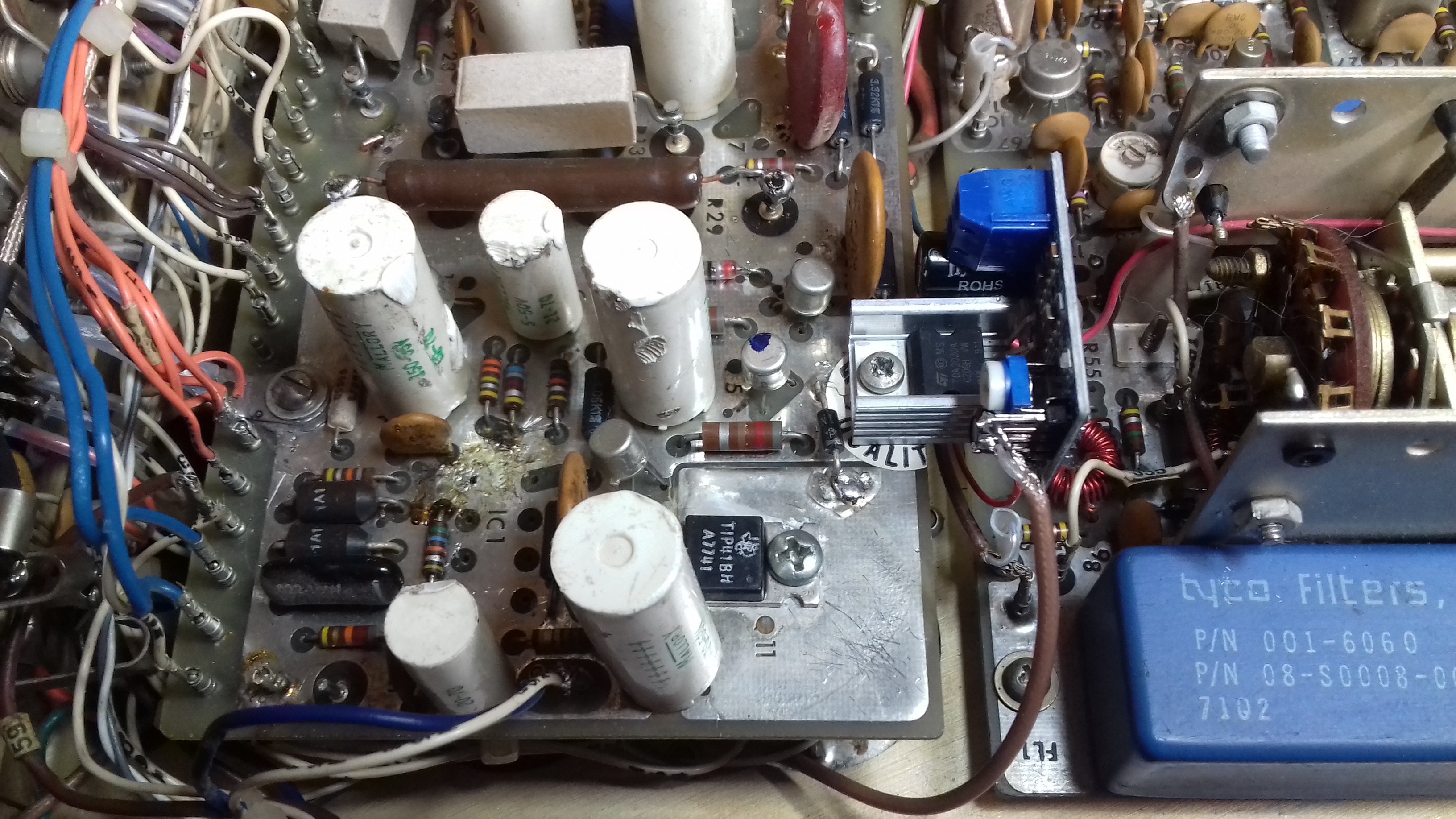
Below the yu can see the new audio board that I installed on the power supply board. It is based on the TDA2030A device, providing clean audio without a trace of hum. Clearly visible is also the place where the old IC1 used to be and the capacitors that someone earlier had "touched" with a soldering iron while desperately working on IC1.
To be continued...
In short, this is current status as of 28 September 2020:
The radio is still not working fully.
- main issue, both VFO's are dead, not giving any output
- dual channel produces noise that can be varied in respect to VFO A or B
- the IF sections seems to be ok, injecting an 8.8 MHz signal at the filters gives audio out and AGC action. AGC fast/slow is working
- RF board crystal oscillators are working
- CW sidetone, key and BK-in is working. So signal out of course..
- when pressing A/T.O. the spot tone is heard and can be varied and the spot level is working
- IF shift is working
- LSB passband noise seems to be ok, USB is very high pitch
Good news, the receiver in the CX7A is now working!
After getting some good and helpful advice from gentlemen on the SignalOne mail reflector I took a closer look at how the VFO's are switched on/off.
It is done by grounding pin 4 on the PTO box and they are muted when -15 volt is applied to pin 4. Measuring pin 4 with a voltmeter reveals -15 volts on both PTO's at all times. At this moment not sure why. So I unsoldered the wire on pin 4 and grounded it - voliá,VFO B comes to life and the digital readout is now showing the correct frequency. Brilliant!
So I started pondering what the absent push button switch "SPOT" is really doing, could it be that it also controls the PTO control line? Not having a replacemen for this switch I decided to take a look in the manual how the switching is done on the S2 Board.
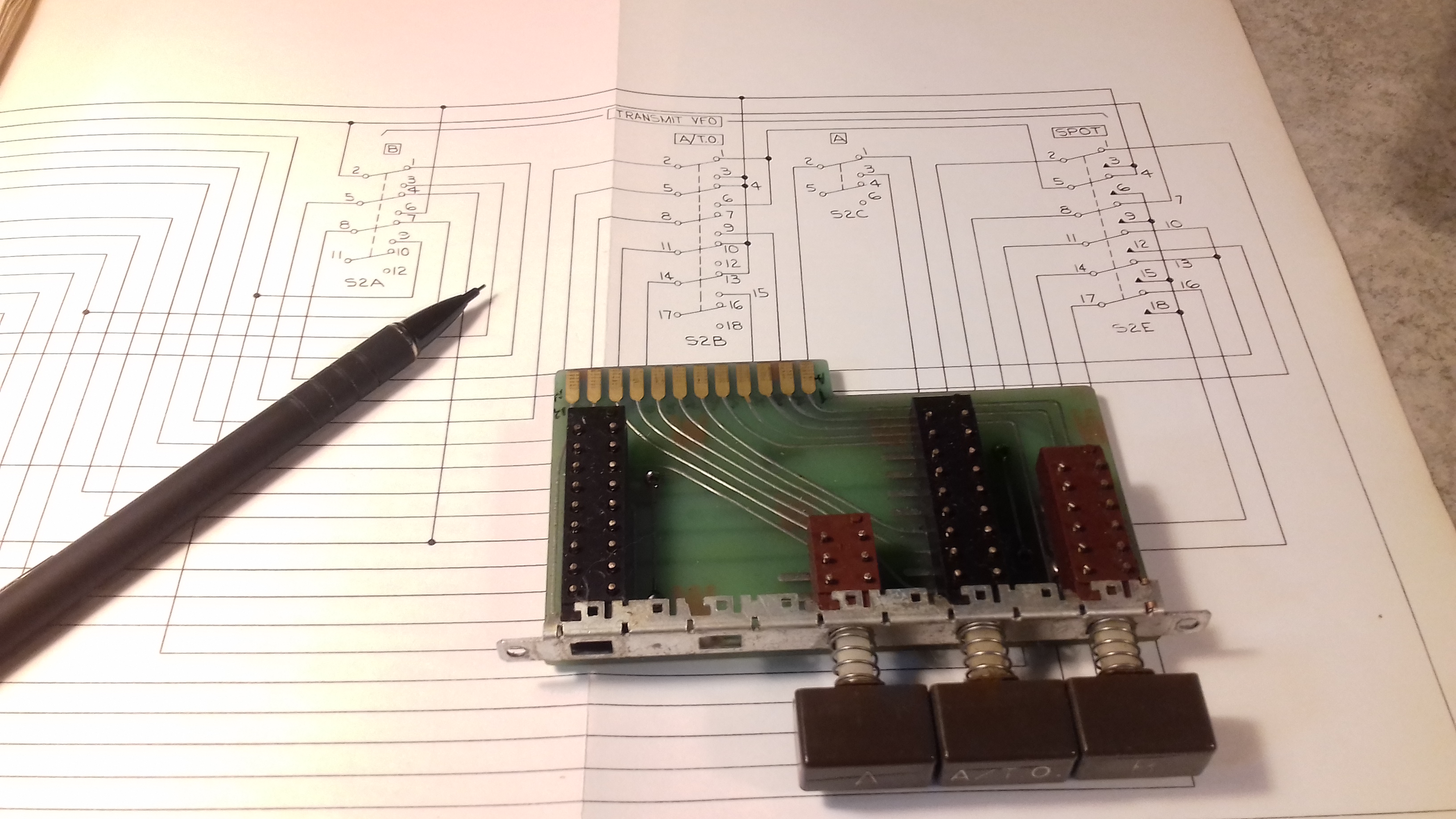
Not having a replacement switch I soldered wires on the back of the S2 Board simulating the SPOT button in idle position.
The radio is now working on receive on all bands - from 80m to the top end of 10m! And the dial is spot on in frequency.
But the receiver is DEAF! Deaf as a post. And the PRESELECTOR is not making much difference.
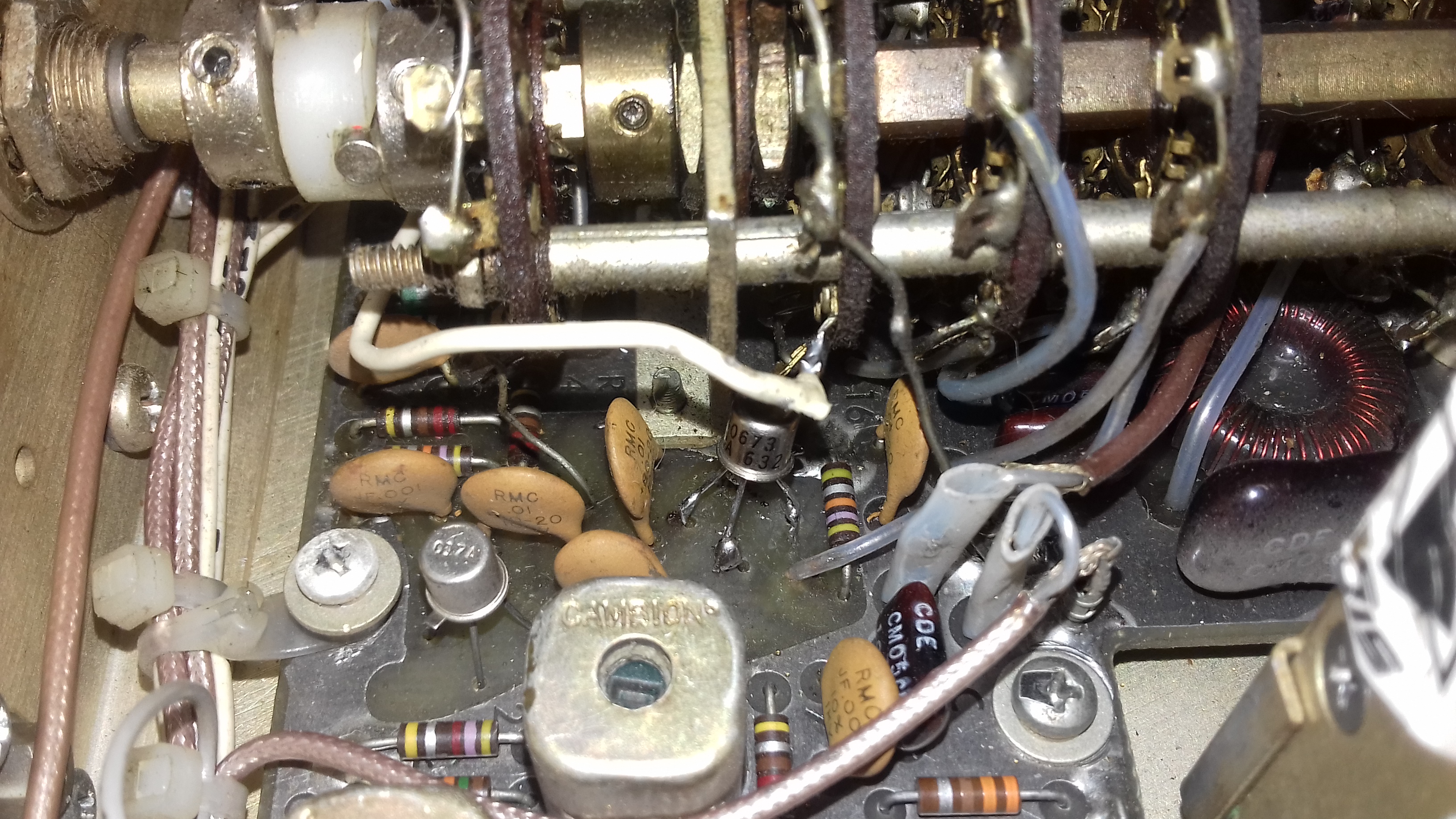
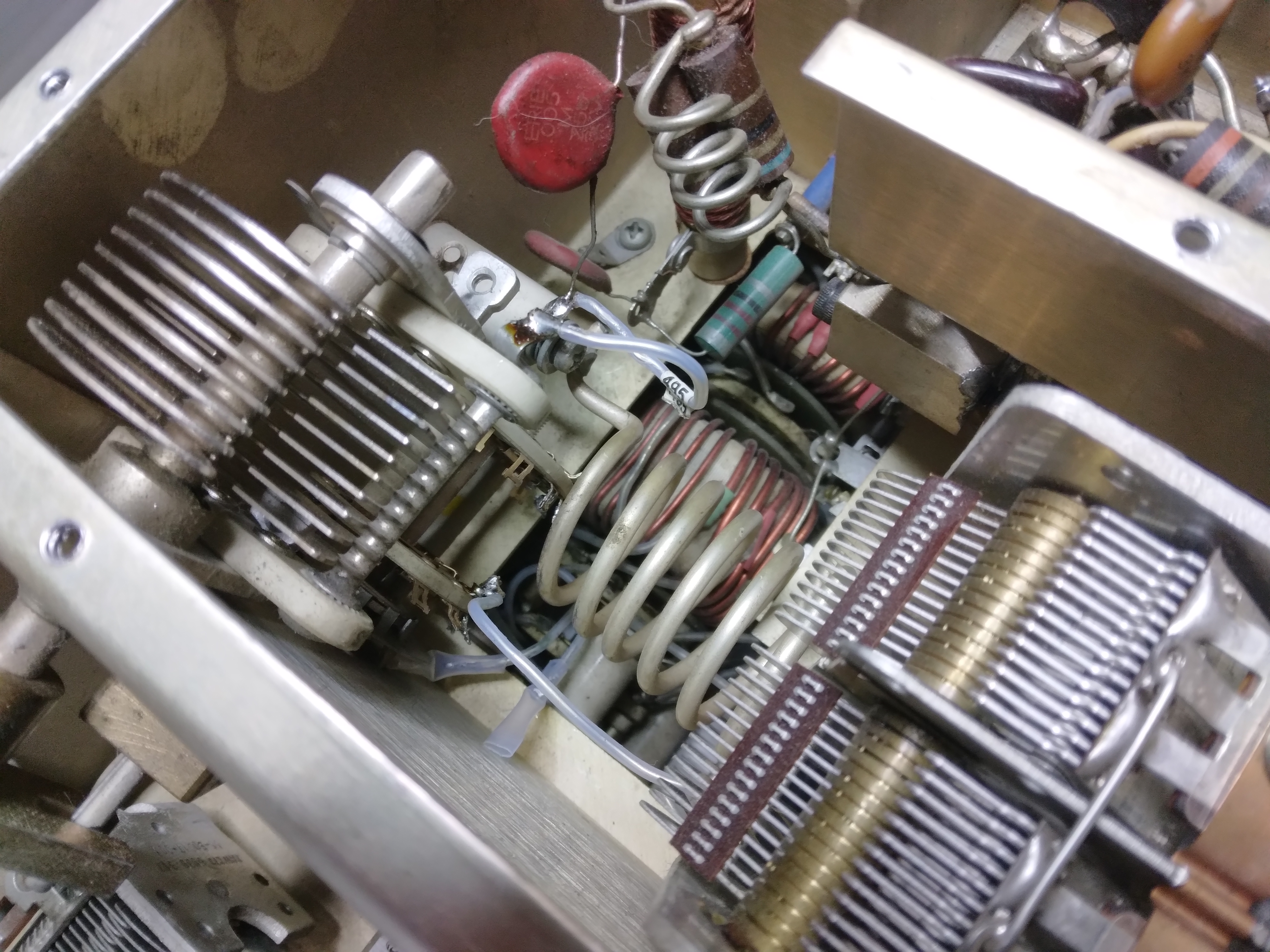
So I locate the front end 40673 on the RF-board and when injecting a signal after this device the signal level goes up some 20 dB or more. So the conclusion is that the 40673 is dead.
It is obvious, as can bee seen in the picture, that this device has been changed before without taking the RF board out. Instead just cutting the legs of the faulty device and soldering a new one to the existing legs. Not having a spare 40673 I replaced it with a BF981 MOSFET. The radio is now sensitive and the preselector is working well, indicated by a very sharp peak.
Here is a video recording I made while listening to SSB stations on 40m this evening
I am quite happy to have come this far today. I can now start concentrating on the transmit side of the radio.
Update 30 September 2020
I decided it's time to take a look at the transmit side. First thing I did was to open the PA compartment to change the final tube. I noted that the coax from the driver board had come loose from the tube socket. So I was glad I started at the right end.
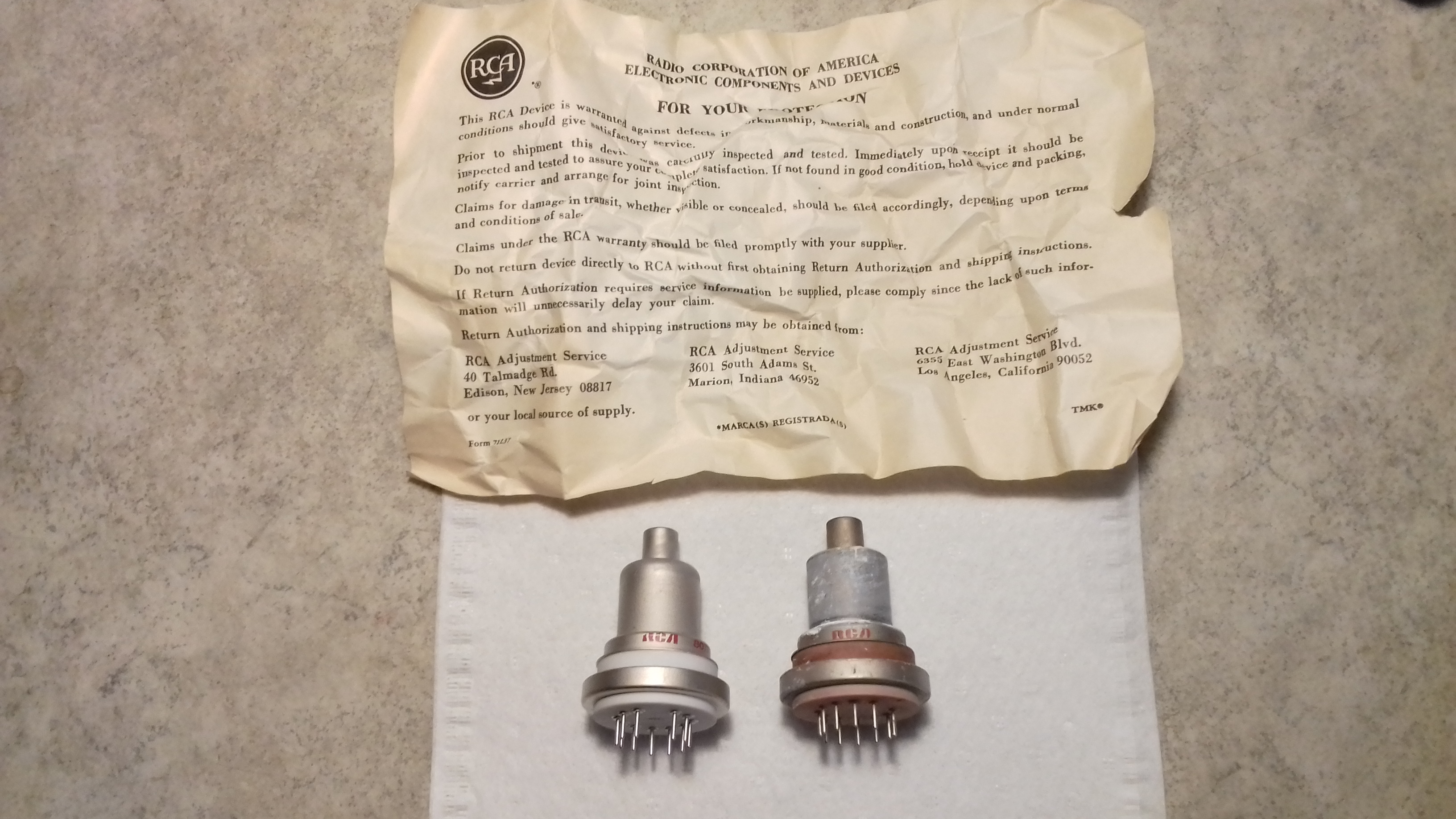
The new tube to the left and the old tube to the right. Both RCA 8072. I think I read somewhere that other brands can have a slighly larger anode diameter that doesn't fit in the clamp holding the tube to the coolling fins. So having a few RCA originals in stock feels good.
After a adjusting idle current and checking a few other things I tried transmitting a CW carrier. I could easily achieve >140 watts output on 80m. A thing that puzzled me at first was that the front panel OUTPUT knob did not have any effect on output power. It turns out that whoever worked on this radio before had reversed the potentiometers so OUTPUT was on the inner control and CLIPPING on the small one in center. Picture was taken when running about a 100 watts carrier output.
On SSB the radio didn't sound too good. It appears that the SSB carrier frequencies are a bit off at this moment.
Still... another step forward :-)
Plenty of time has passed since the last update. I have been working on this battered CX7A off an on during the past few months.
OUTPUT/CLIPPING controls
The problem described above with the OUTPUT and CLIPPING potentiometers were more of the same clumsy things that has been done to the radio by an unknown clown. The two pots were not connected properly and one side of the CLIPPING pot was grounded where it should not be grounded. Below is the cleaned up connections to the two potentiometers.
After this the OUTPUT is conveniently varying power from zero to full power and the CLIPPING adjustment is also working as it should.
Setting voltages on RF board
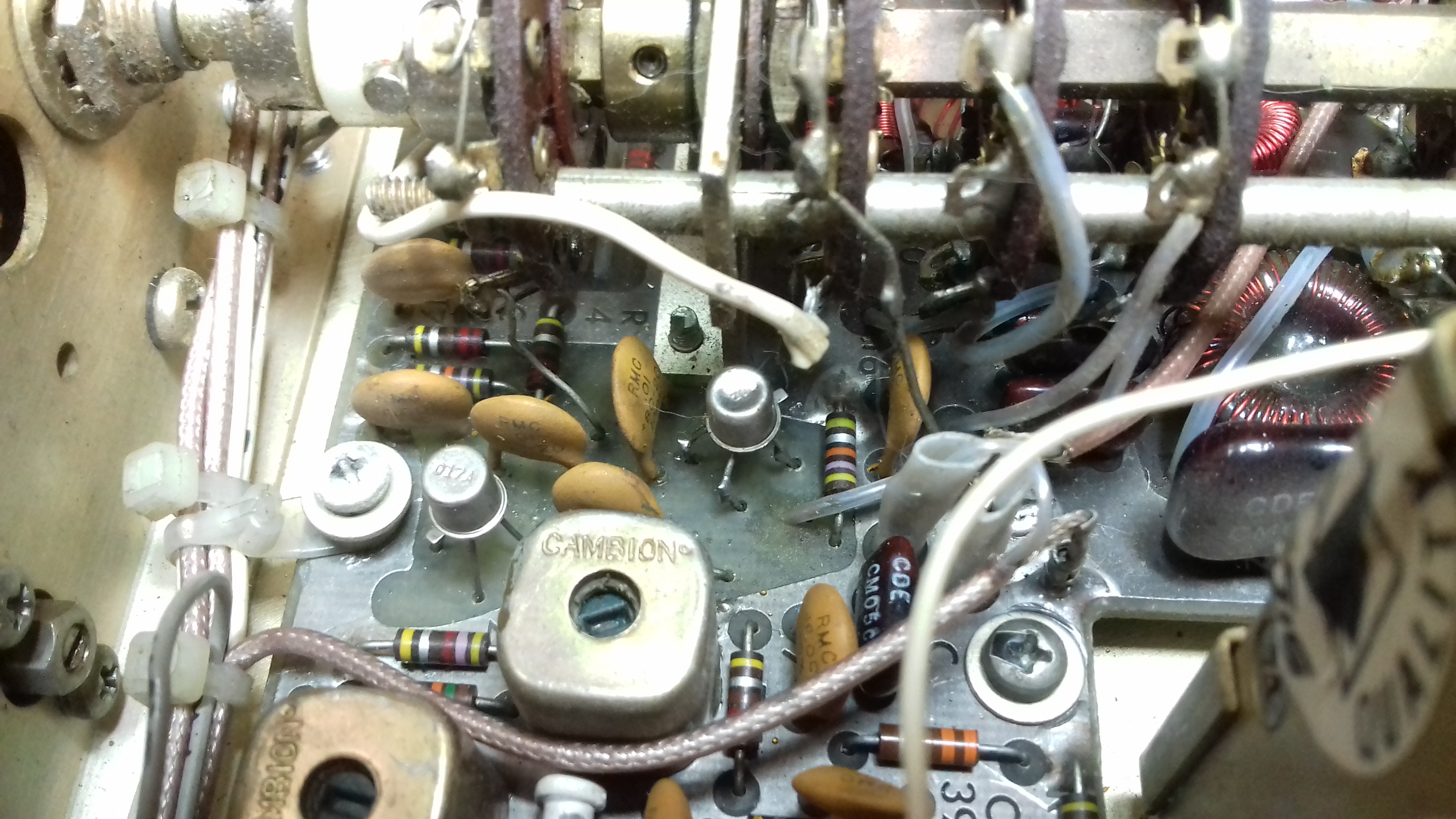
On the RF board I've had difficulties setting zero VDC on the collector of Q5 via R43 and final tube bias with via R19 as per alignment procedure h.6 on page 5-9 in the service manual.
After very careful examination of the RF board I found a problem. A disc capacitor was bent over and fully covering resistor R7 on the board. When I lifted the disc capacitor I noticed that one leg of R7 (seen next to the big disc cap in the center of the photo) had been hit with great force and the leg was now grounded to the PC-board.. Again, who ever worked on this set before had been "hard at it" for sure..
After carefully lifting the leg of R7 up I was able to set voltages controlled by R34 and R19 to the correct values.
PA module
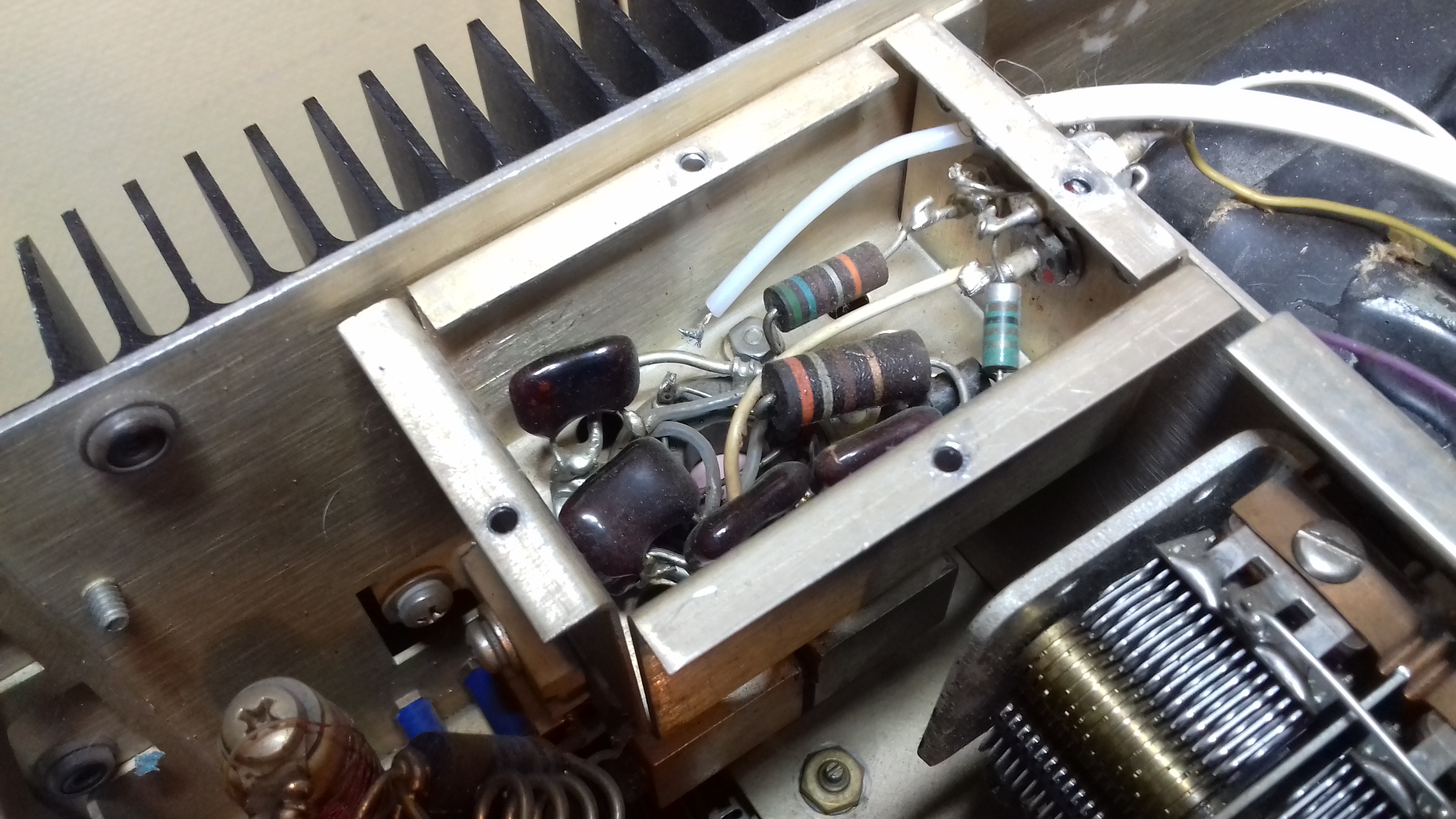
I added a high voltage capacitor in series with the drive power coming from the RF-board to protect the driver transistors in case of a short between the anode and G1 of the final tube.
In the picture you can also see the brand new (NOS) RCA 8072 tube in place.
Fuses
A suggested in Bob Sullivans "Signal One Trouble Guide" I have installed fuses for the tube HV and G2 and also for the Nixie tubes/counter board in the digital display. The display unit also has 200 volt zener diodes installed to protect it from excessive voltage.
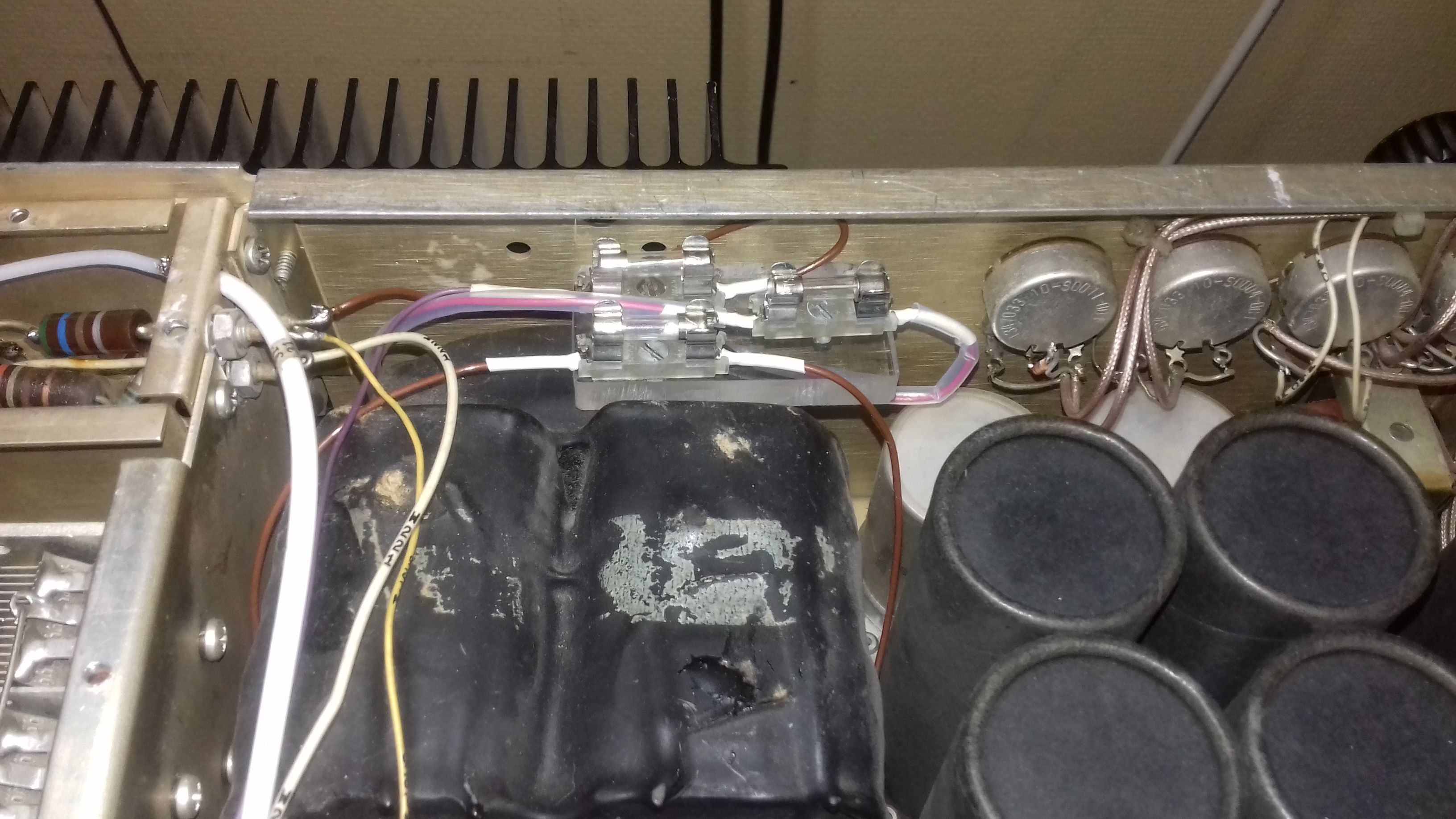
The fuses are on a piece of plexiglass attached to the rear panel. The high voltage line is connected via teflon insulated wire placed inside a small size teflon tube.
AF Audio
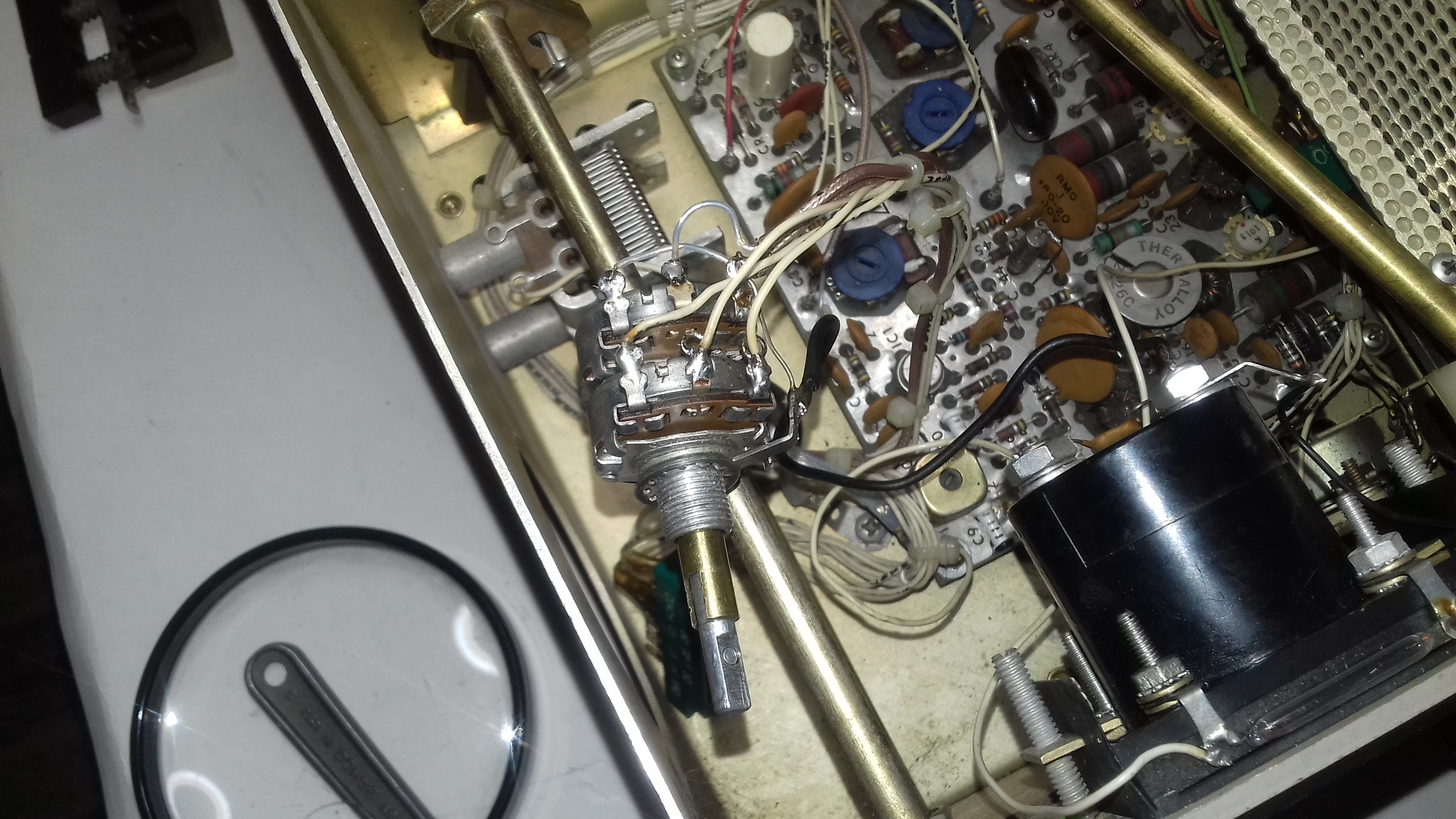
The AF gain potentiometer was not in good shape resulting in intermittent and crackling audio as the level was adjusted. The pot is again a dual pot with RF gain on the inner side. As these type of potentiometers are very difficult to find in Sweden I tried a different approach by rebuilding the existing pots instead. On an auction site I was able to place the highest (bargain) bid on a set of dual type concentric potentiometers. From one of these I was able use parts to rebuild the CX7A AF gain pot.
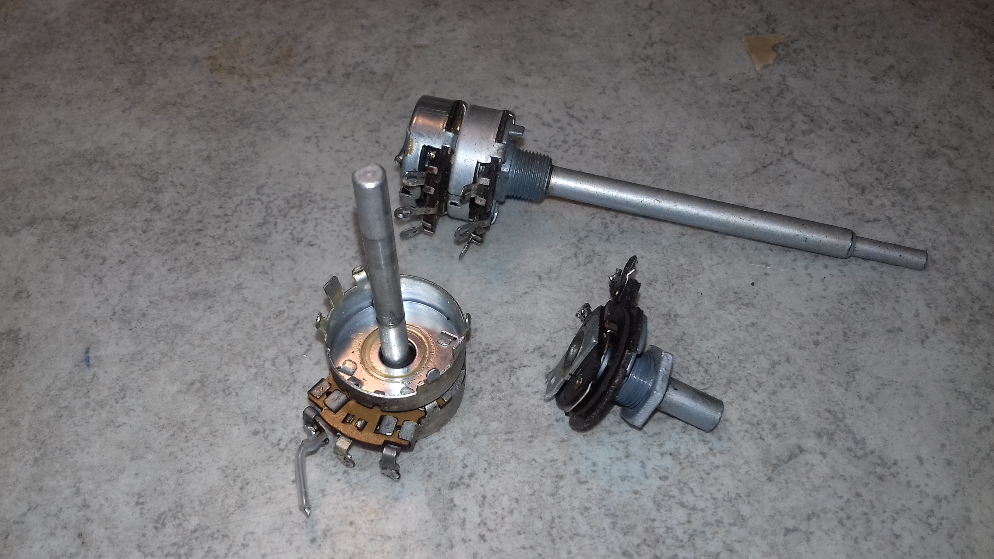
By using the the carbon track, which is RF Gain on the original pot below inthe picture above, to replace the top carbon track on the pot I bought I was able to build a new fully functioning AF/RF gain control with appropriate resistance values. After cutting the shafts to the correct length and installing it in the radio the AF control is now smooth with no cracks or intermittent jumps.
As the new audio board doesn't need the output transformer I have rewired the headphone jack accordingly so that the loudspeaker is muted when headphones are used.
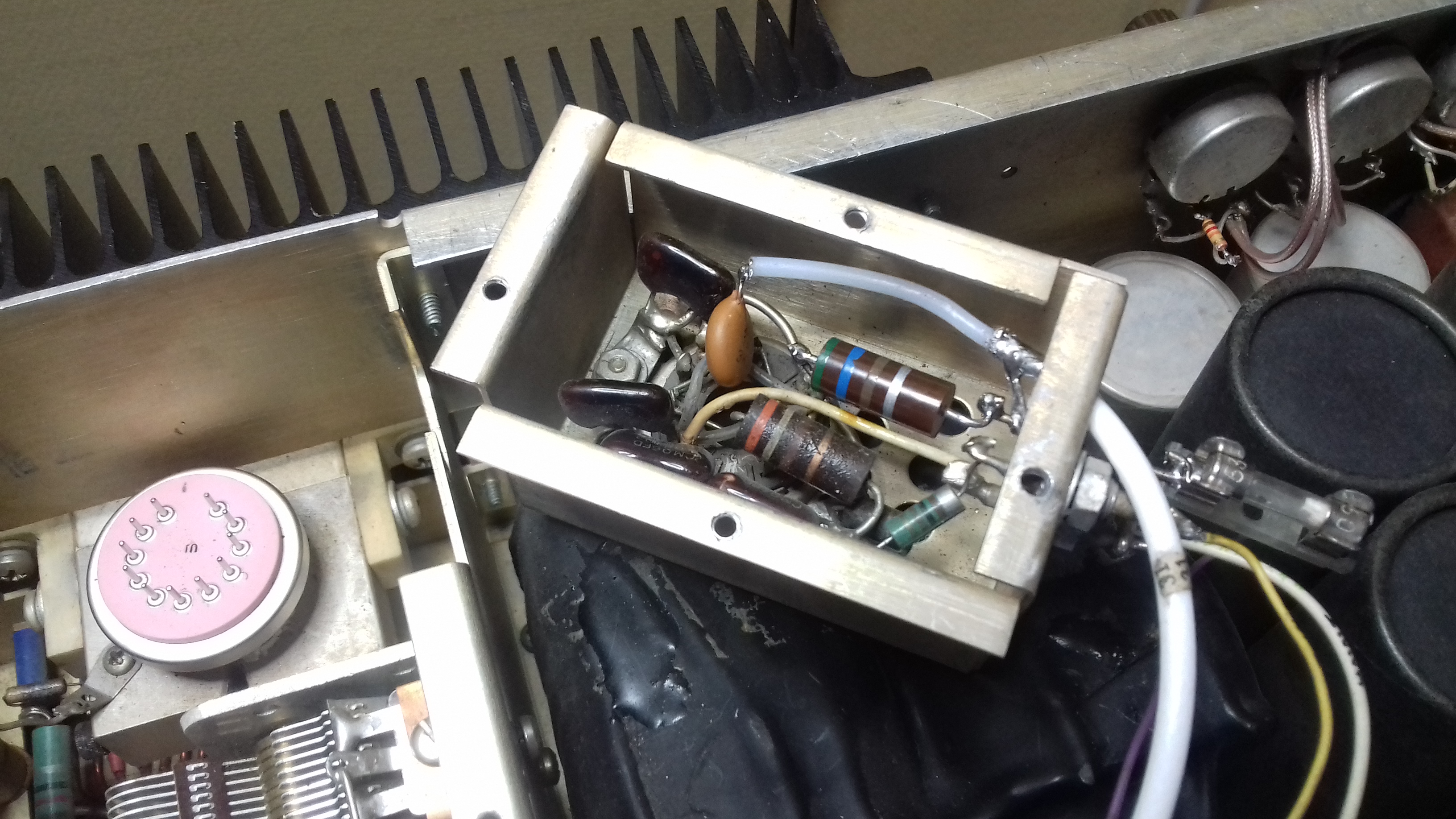
CW sidetone
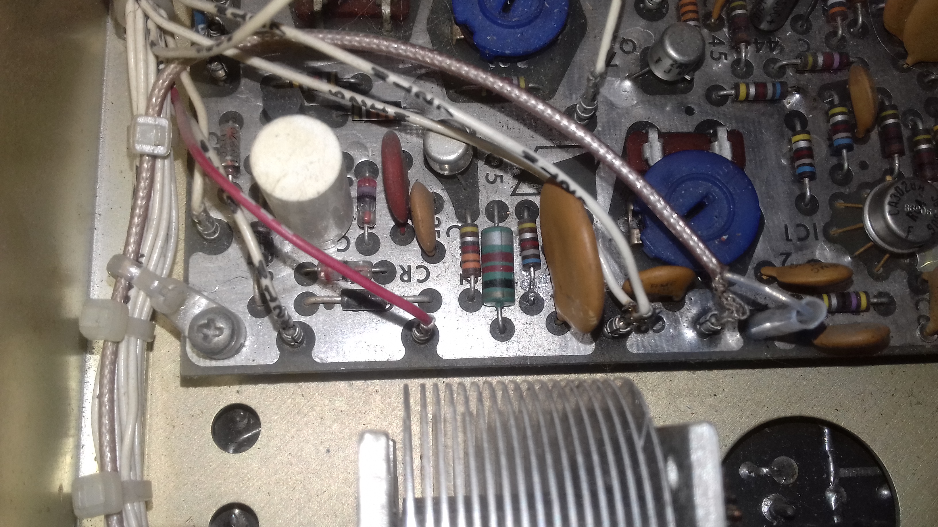
When switching the rig to CW there was a continous tone in the loudspeaker. It was clear that the sidetone was switched on constantly. Tracing the sidetone control circuit and the sidetone audio path on the schematic lead me to transistor Q4 on the Audio board A6.
The transistor was shorted. I did not have a similar 404068A MOSFET in stock so I replaced it with an MPF102. The sidetone functionality is now fully restored.
SSB audio
The carrier oscillator on the BFO-board has been adjusted to give both sidebands good audio. The BFO board is placed below both the AGC and the Audio board and is therefore not easily accessible. But the control R46 can be accessed with a long screwdriver via holes in the AGC and Audio board as can be seen below.
RF front end
As mentioned earlier in this document the front end MOSFET 40673 was replaced with a BF981 MOSFET to get the receiver going. Since then I have acquired a couple of 40673 devices so the front end BF981 is now replaced with a 40673. This improved sensitivity somewhat.
Status as of 18 February 2021:
The CX7A is now performing well. Sensitivity seems to be ok even on high bands but more alignment and measurements are are needed so I can fully verify performance. But compared to my own CX7s receive side, this one is almost as good. But not as good yet... :-)
The transmit side is also performing well. I would appreciate some tips on how to modify the rig so that it can make use of the VOX circuit to run BK-in on CW rather than QSK. I have tried my own MacGyver solution by feeding sidetone audio into the vox circuit on CW and that works. But it is not really an elegant solution.
This radio is still missing the SPOT-switch and the AC ON/OFF button so I am looking for these parts. Plus a cabinet if anyone is willing to part with such a thing...
I could not be more happy!
The missing parts described above arrived some weeks ago, all the way from Texas. It's Fred, K5OG who kindly offered to send the SPOT switch assembly, the missing SPOT/AC buttons and best of all, a beautiful cabinet including the bar/stand that raises the front of the rig up. I am forever in debt to Fred for this kind gesture - there is no way that I could have found these parts in Sweden.
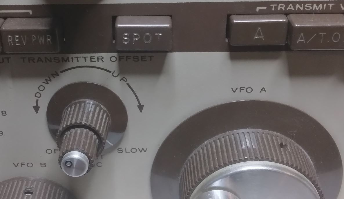
The SPOT-switch is an important part of the circuitry. It not only activates the two VFOs, it's also used to set the transmitter offset which is especially important in CW when using just VFO A in transceive mode. As shown above, I have so far simulated the SPOT switch in recessed position by bridging the correct pins on the assembly. Therefore I have not been able to set any transmit offset or even check the setting of the offset potentiometer.
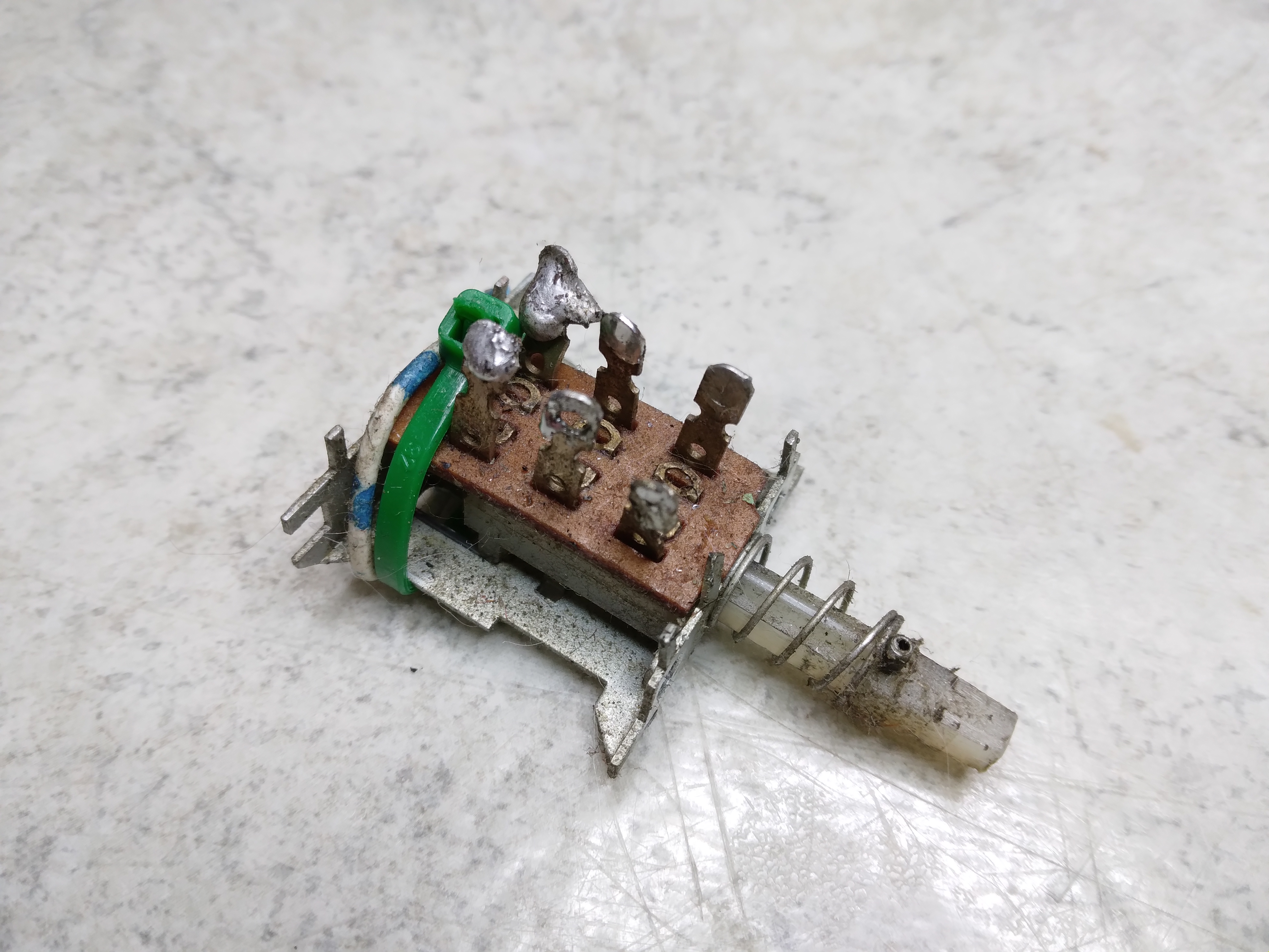
Spot switch assembly repair
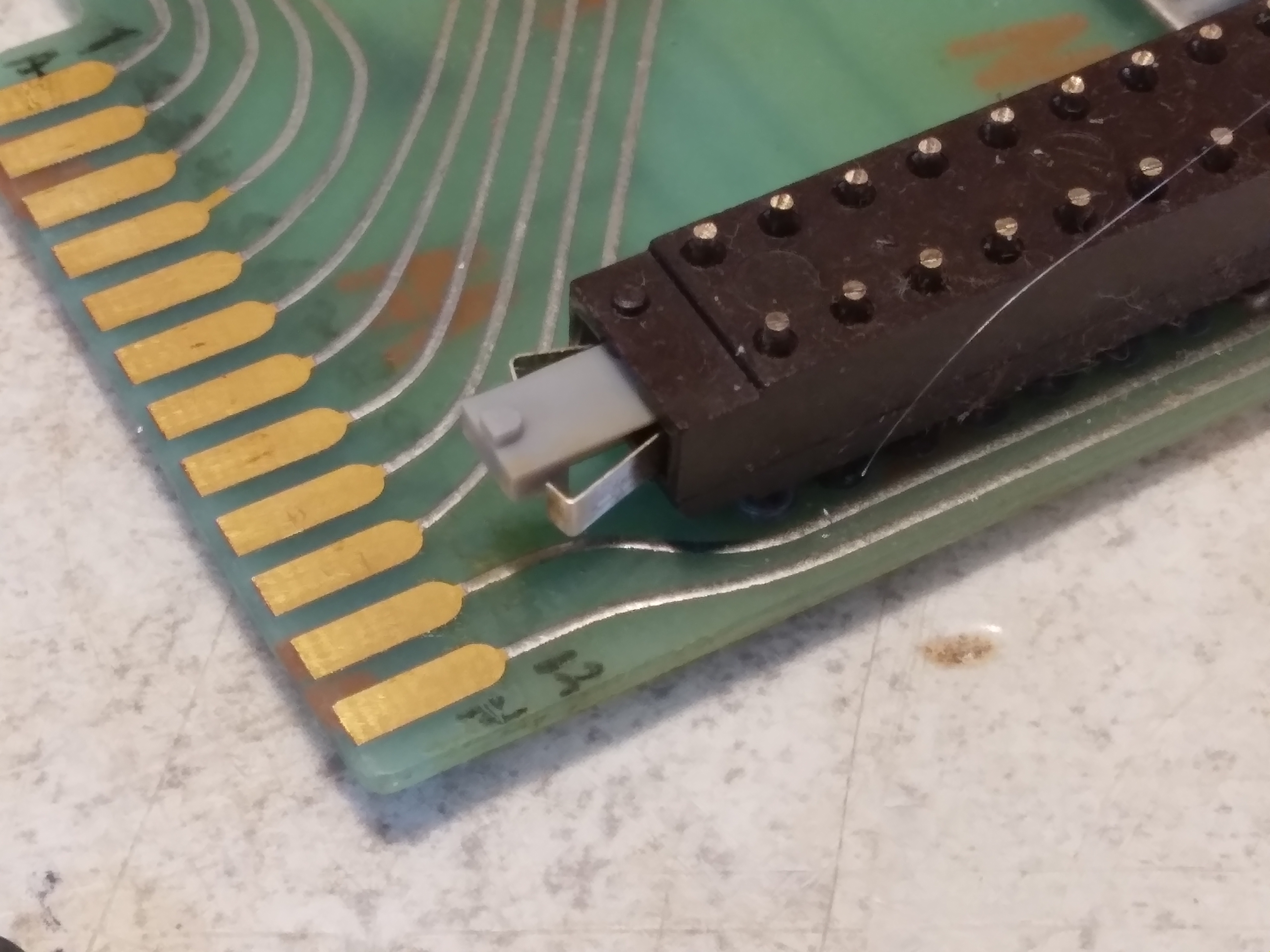
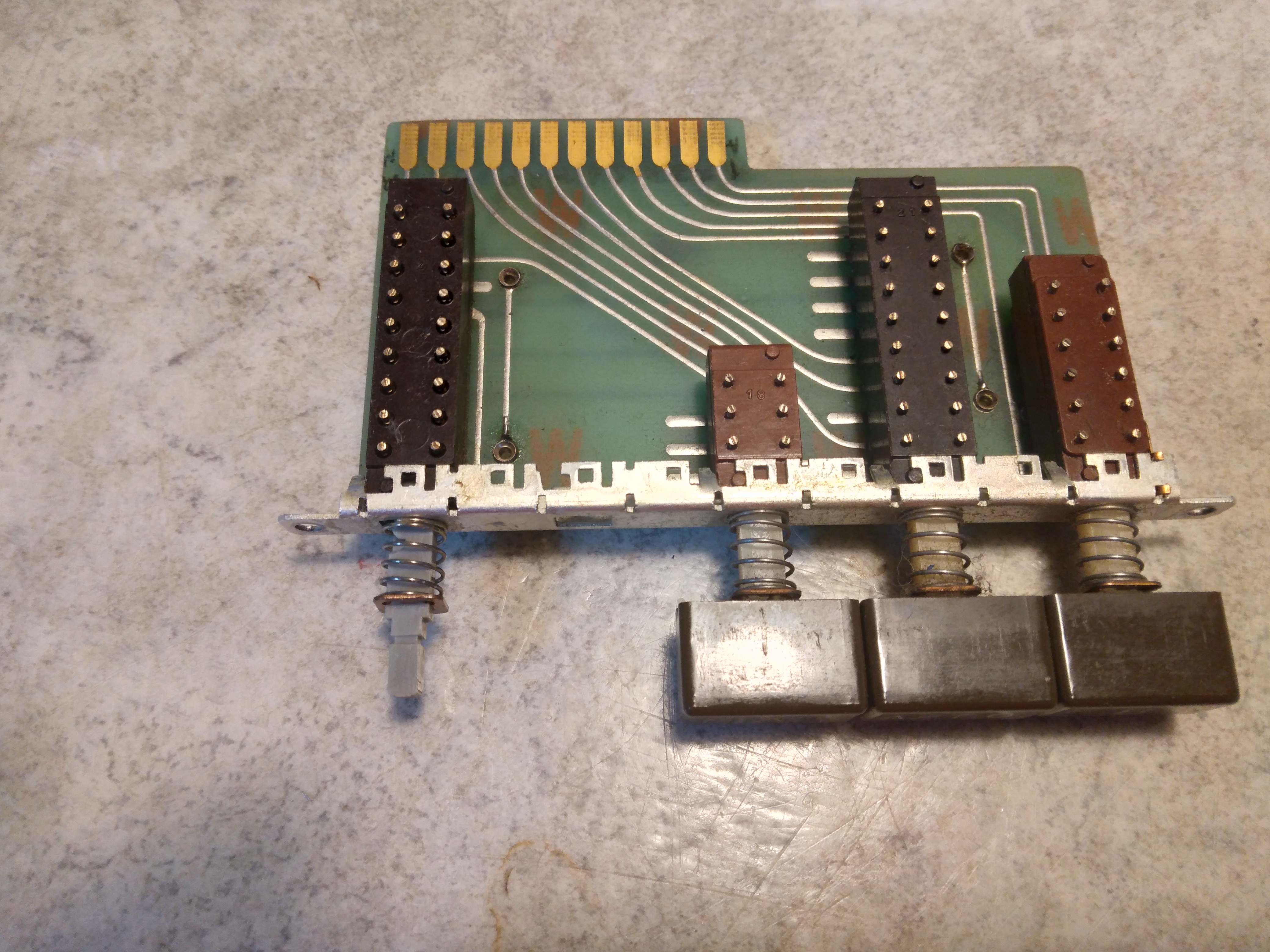
The SPOT switch and transmit VFO control buttons are placed on a board that sits below the Nixie-tube counter assembly. To get access to the switches the counter and a few other parts are moved. The switch assembly is then easy to bring out of the cabinet as it has a CINCH connector on the back.
Here we can see the new switch is next to the board with the SPOT switch to be replaced to the right, missing it's interior parts.
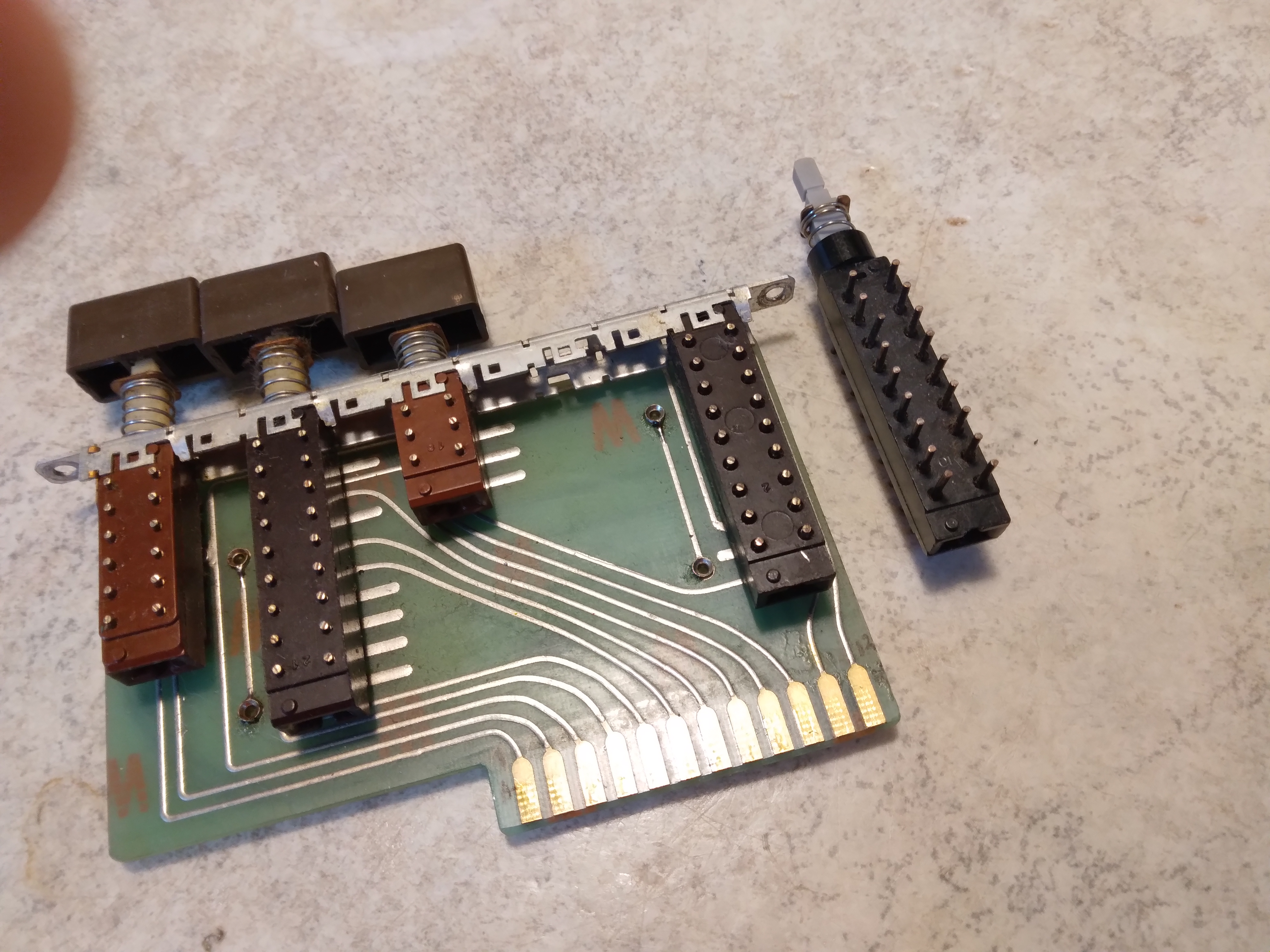
I realized that I had two options - desolder the old switch from the board and replace it completely with the new switch - or take the new switch apart and put it's interior parts into the old switch.
After some consideration I decided to keep the old switch in place and put the interior parts of the new switch into the old one. This is mainly because the switch is soldered to both sides of the board and I did not want to create any problems by trying to desolder it. Also, the pins of the new switch would have to be trimmed down - at the risk of actually cracking the plastic.
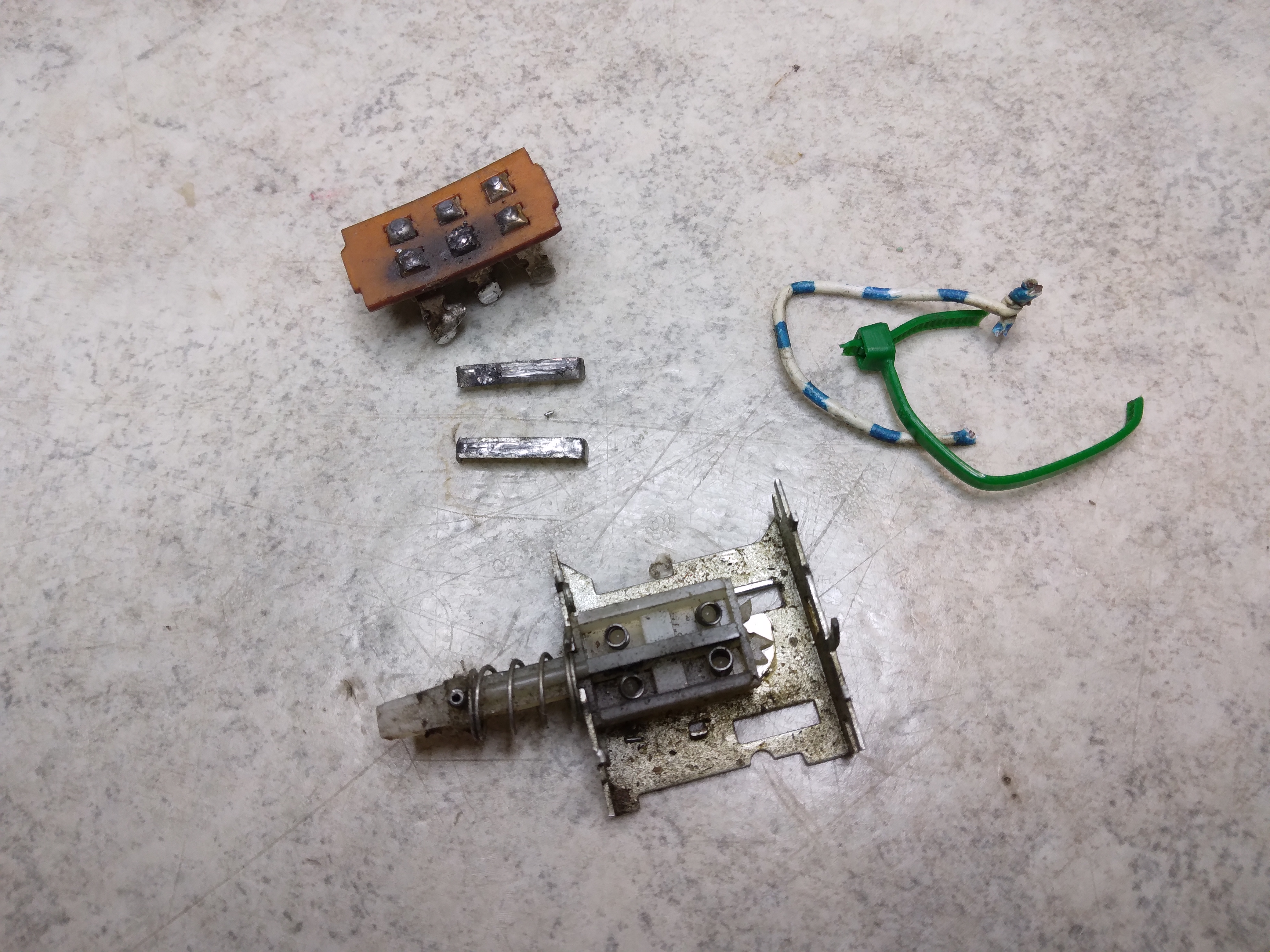
So I put my best goggles on, took a deep breath and opened up the new switch to see what was in there..
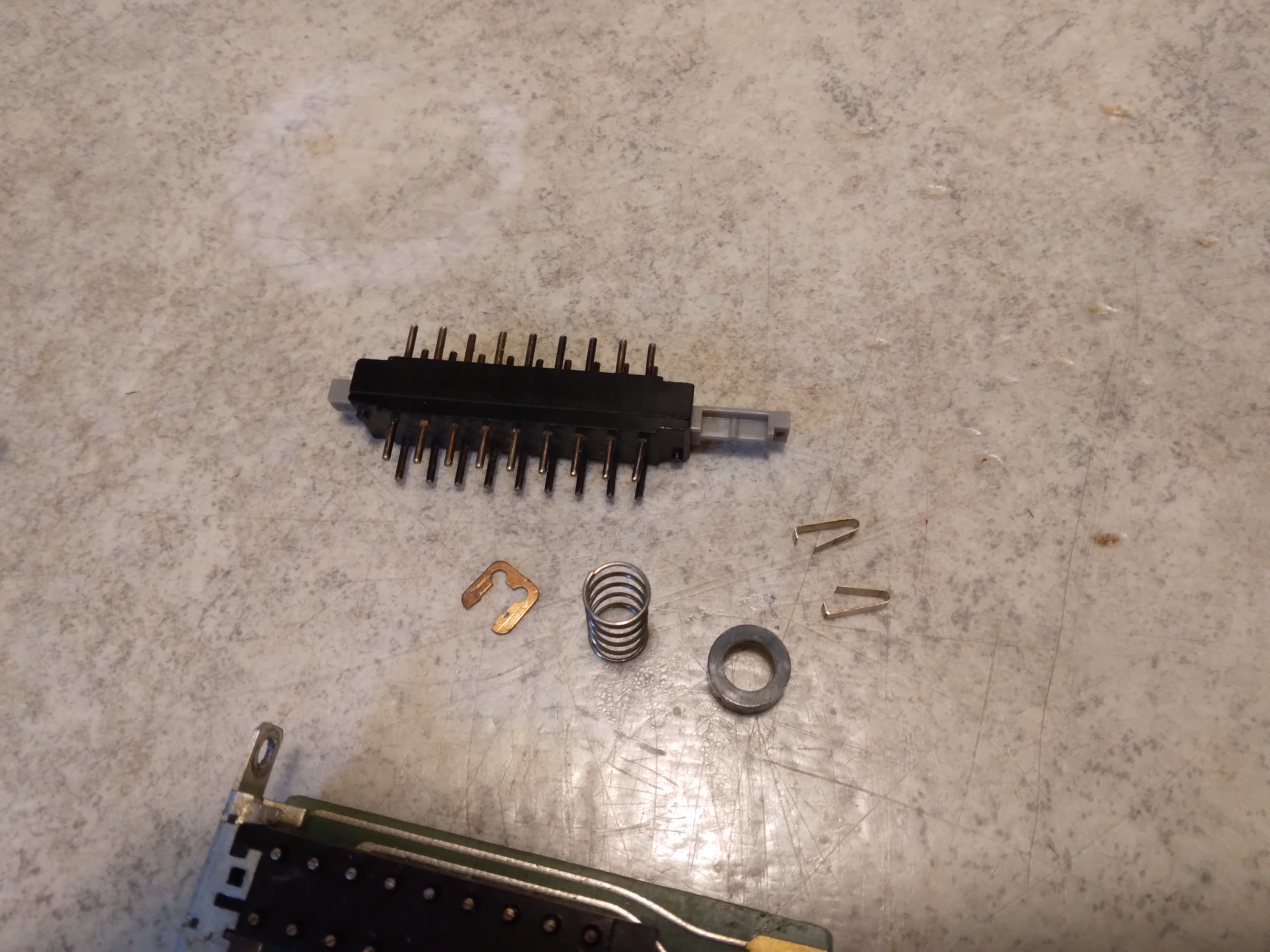
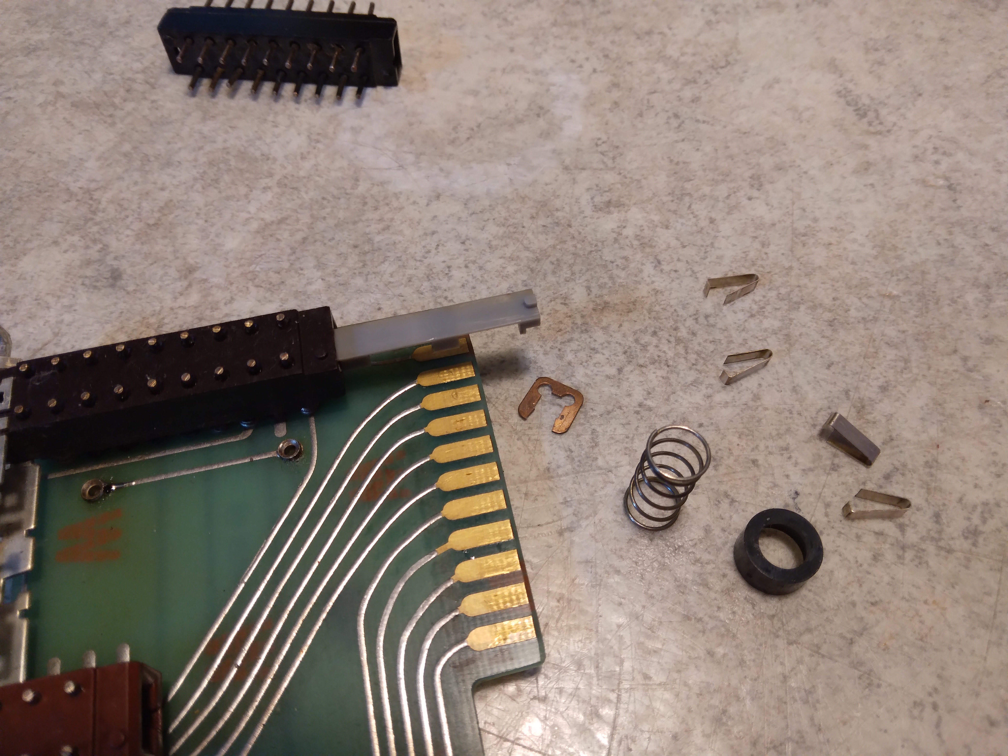
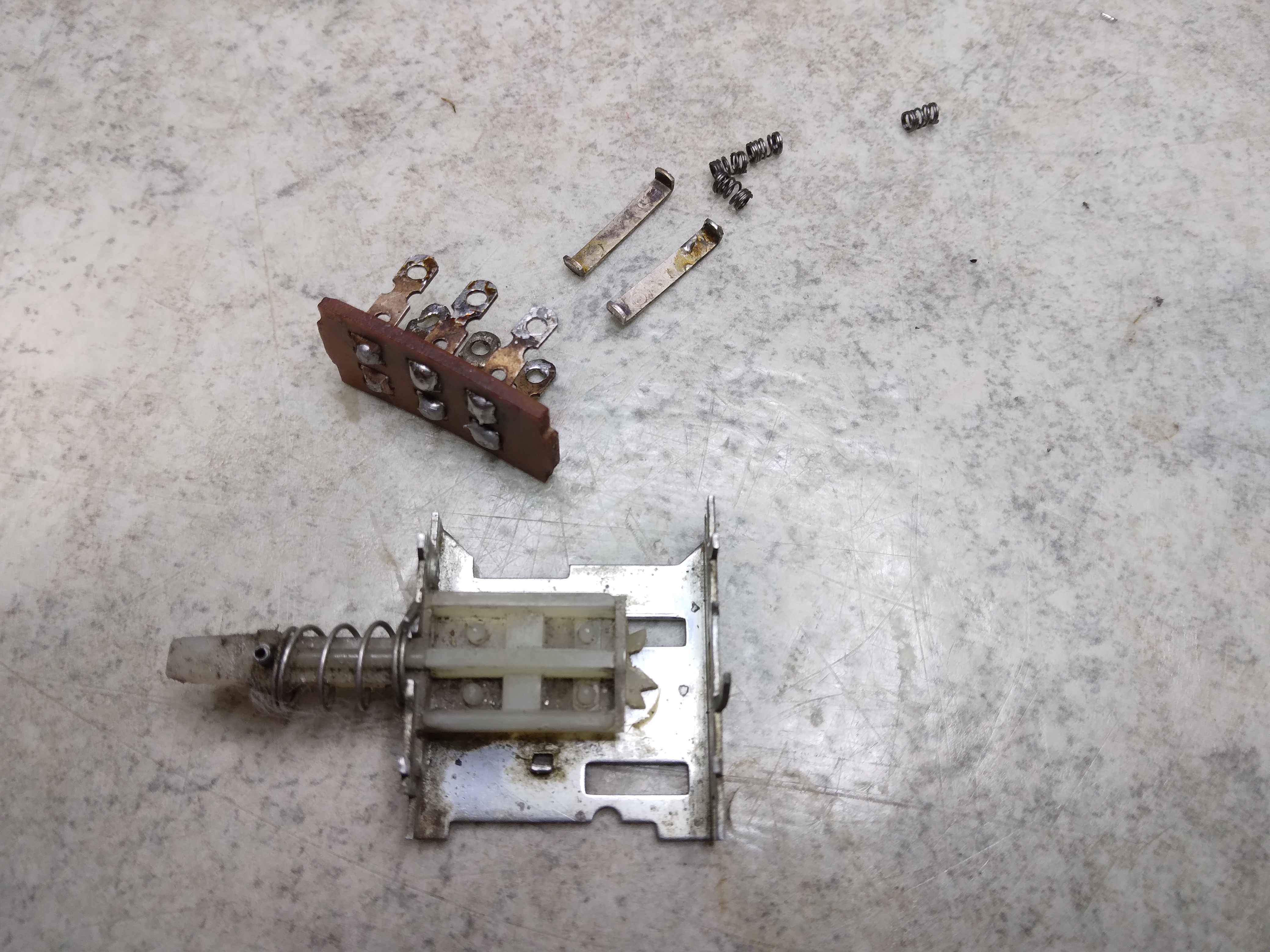
Above you can see the parts that are going to be transfered to the existing switch and below you can see that the process is started.
The tiny clips are what is actually connecting the different pins. They have to be positioned correctly for the switch to operate as intended. Some more closeups below..
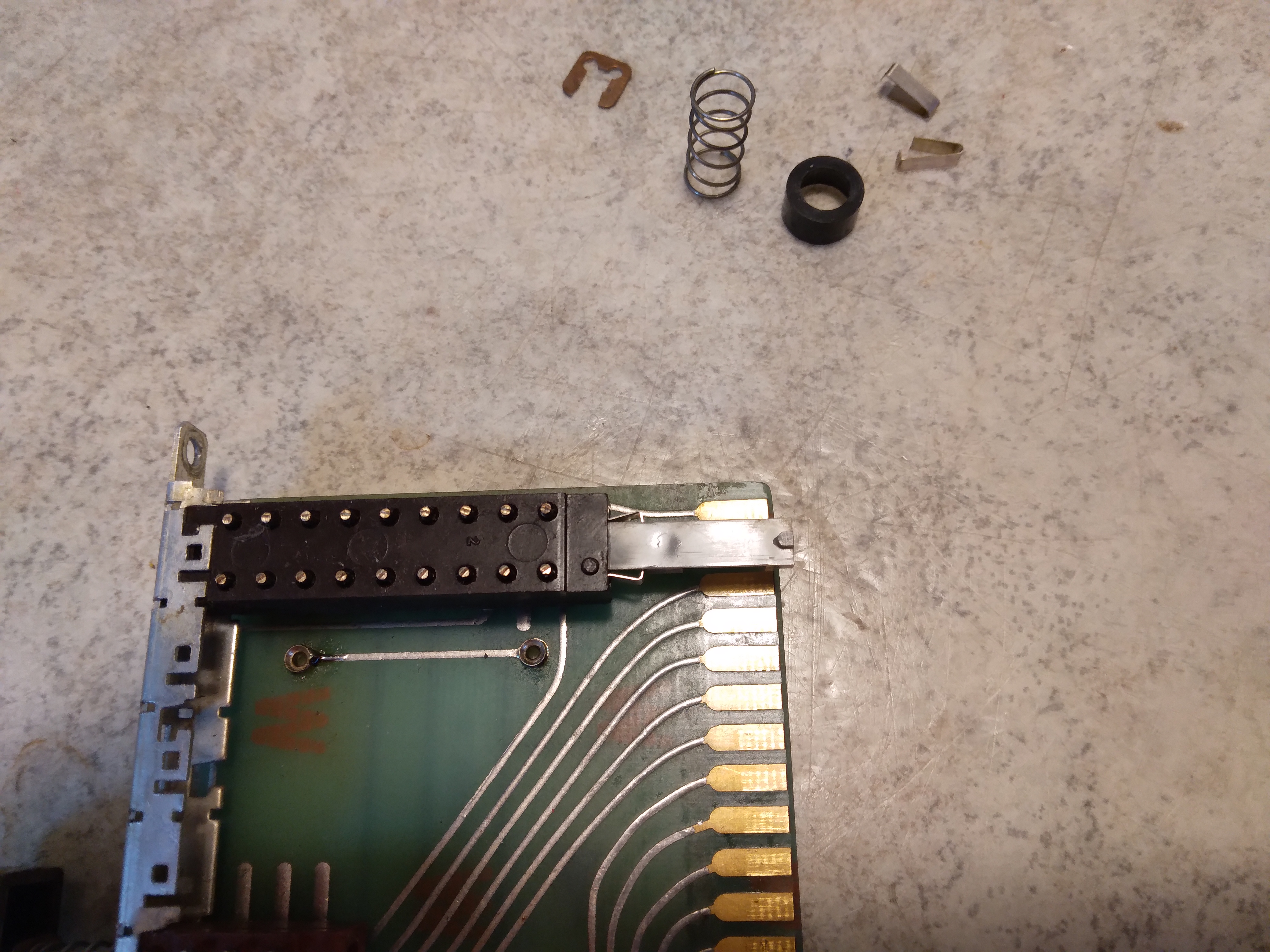
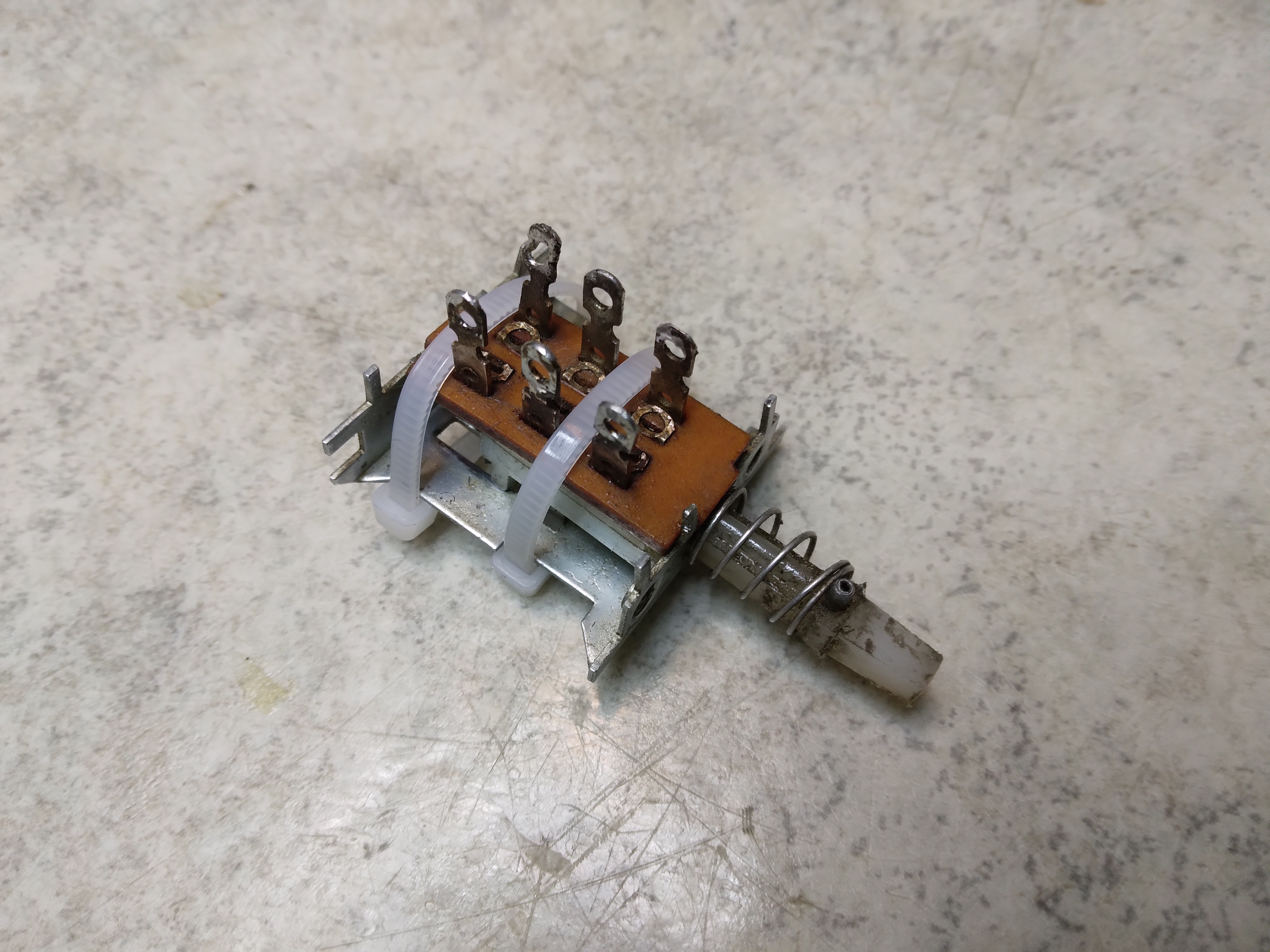
Almost done..
Done!! The SPOT-switch is now repaired and the board will be going back into the radio.
Above a closeup of the VFO buttons - no gaping hole for the SPOT switch any more.. and below is a picture of the AC switch, now with a nice original button courtesy of Fred K5OG.
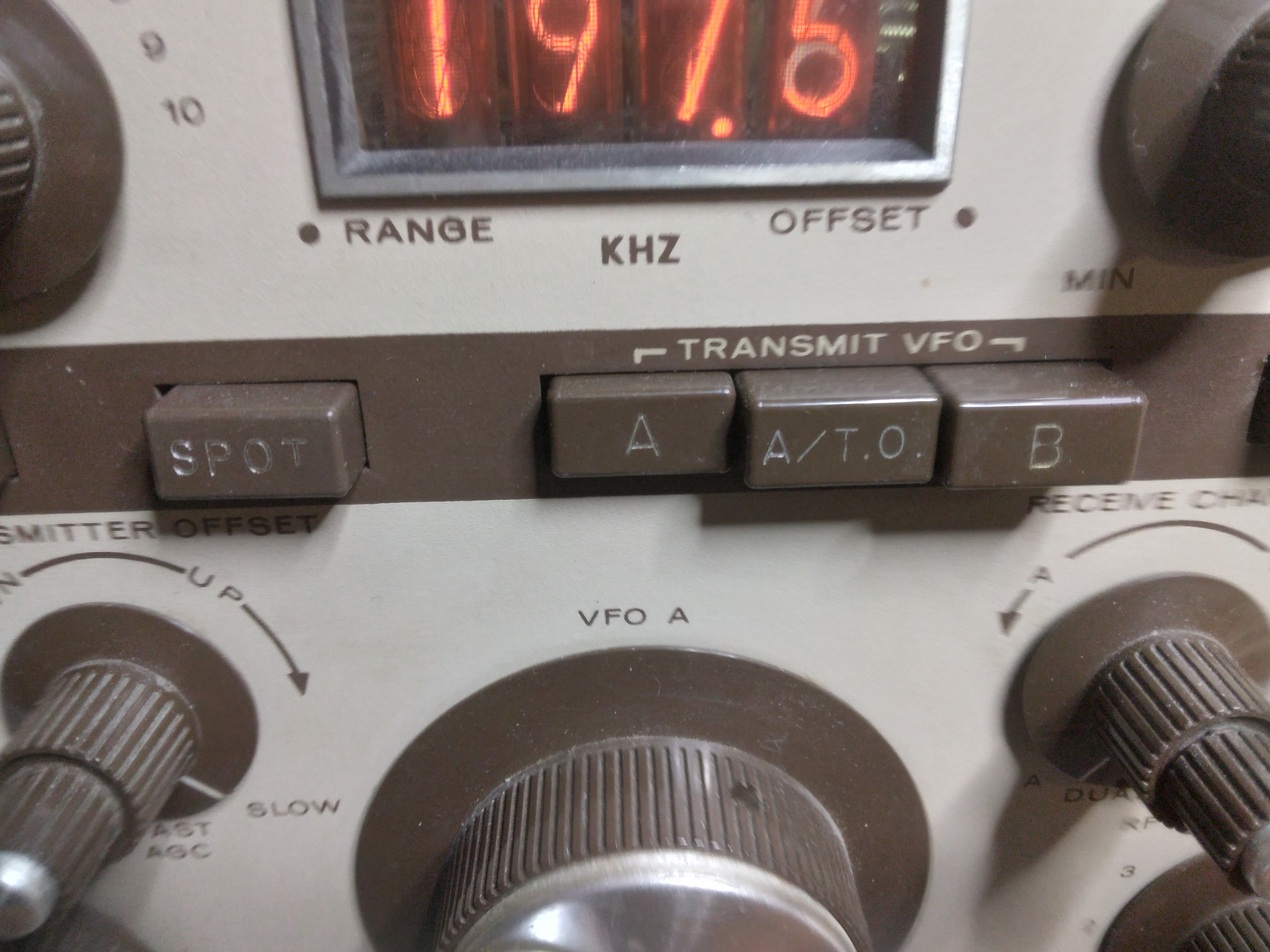
Setting the transmit VFO offset - A/T.O.
Now that hte SPOT switch is working there is a way to check the setting and range of the transmitter offset potentiometer. It is located in the centre of the AGC switch, just below the SPOT switch, see the picture below
With the button A/T.O. button depressed the transmitter offset can be adjusted. You set it the pitch/offset by listening to the tone when the button is activated. In this radio. I soon noticed that the offset zero beat, which is supposed to be close to the mid range of the offset pot, was not correct. I could not set a zero beat even with the pot at it's lower limit.
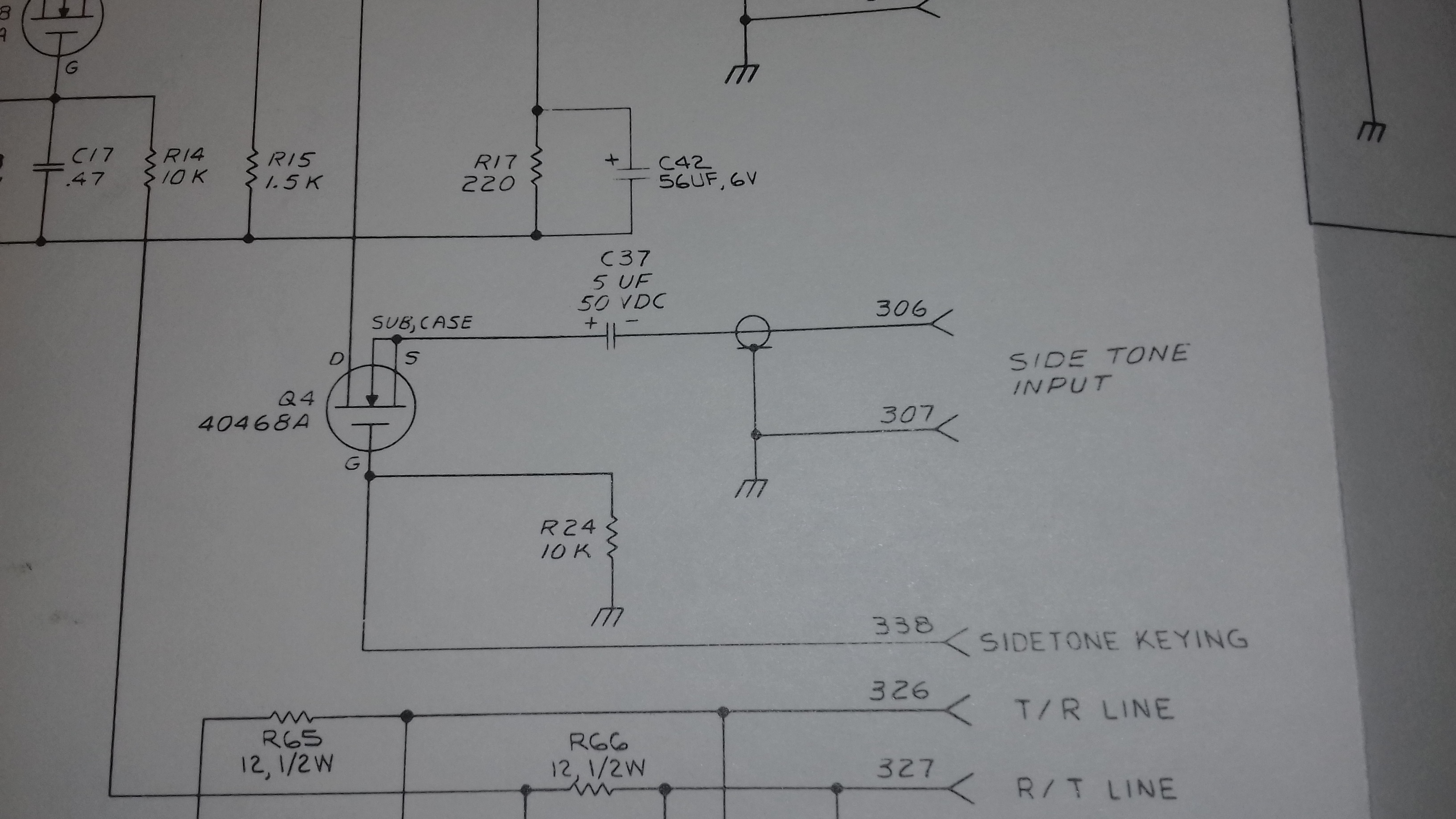
This offset is controlled by the BFO board. On this board there are three components that affect the range of the front panel potentiometer. The manual show them here:
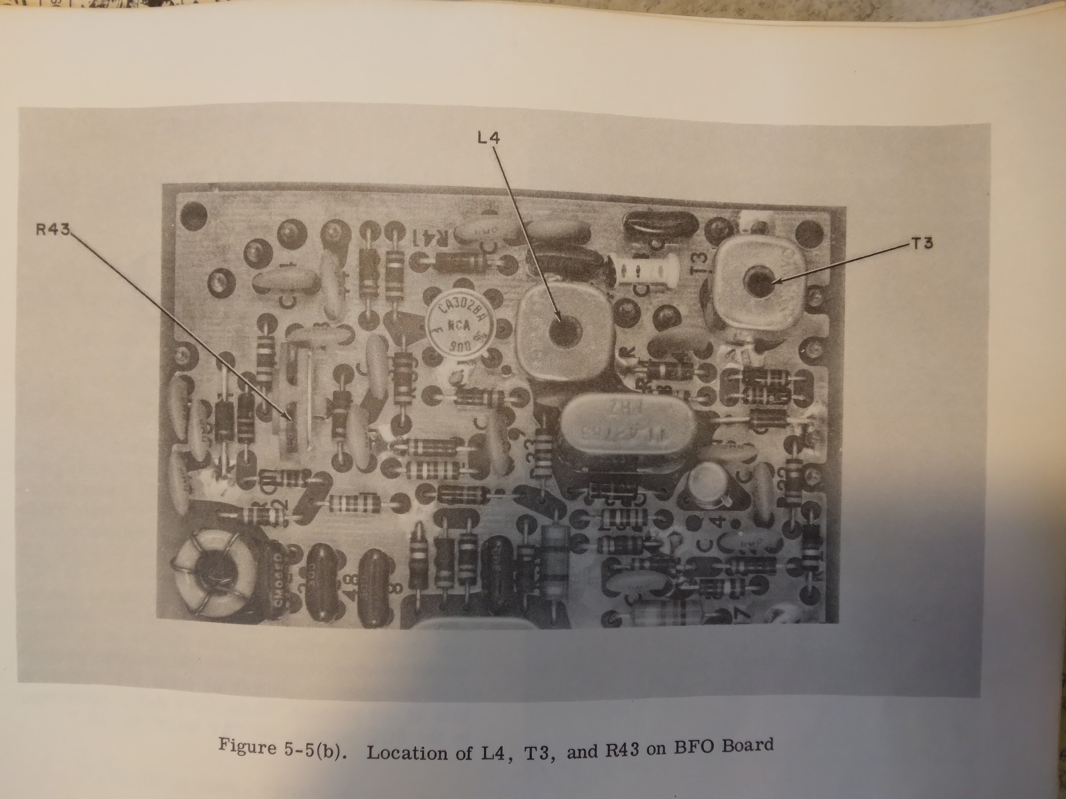
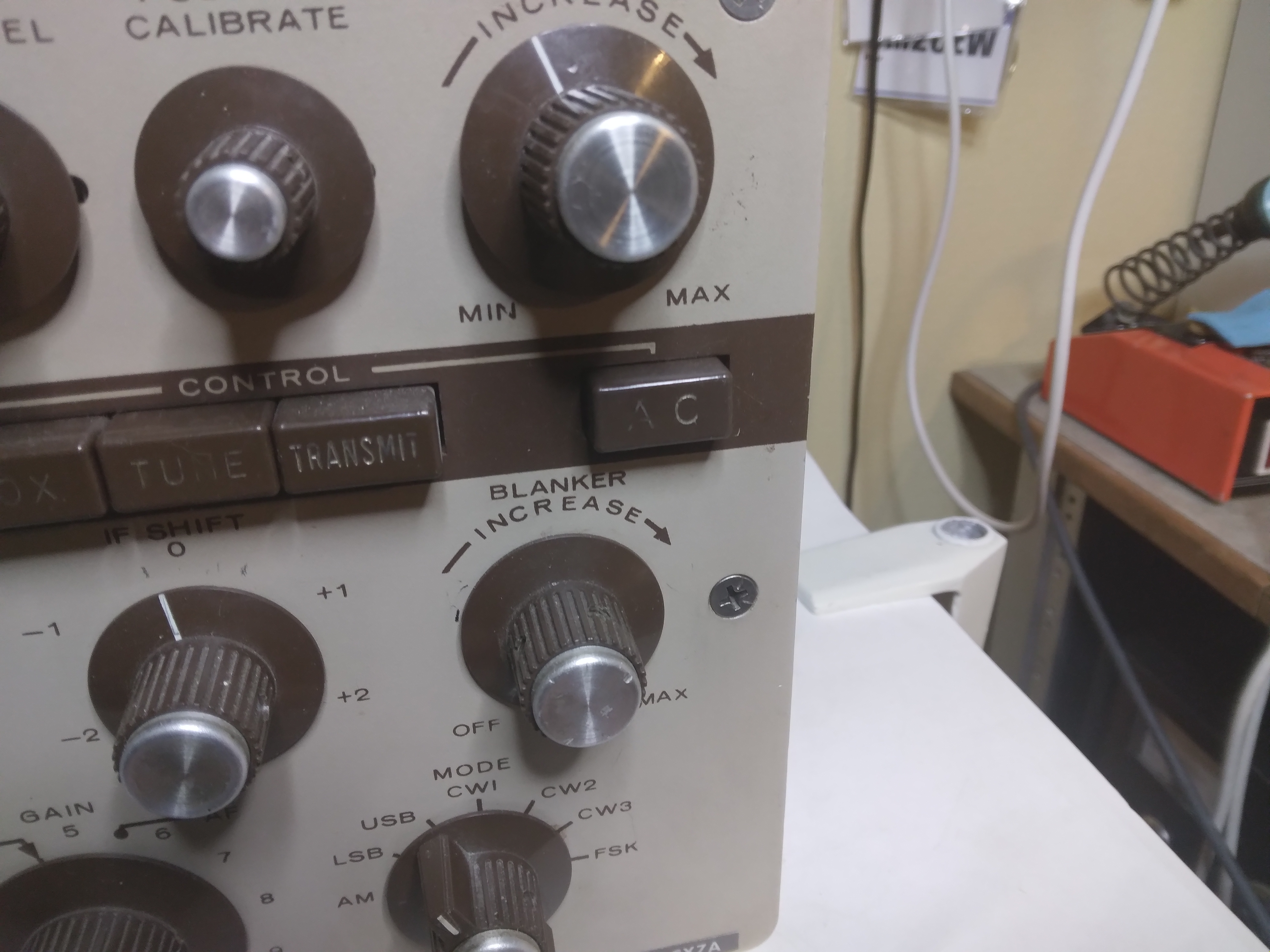
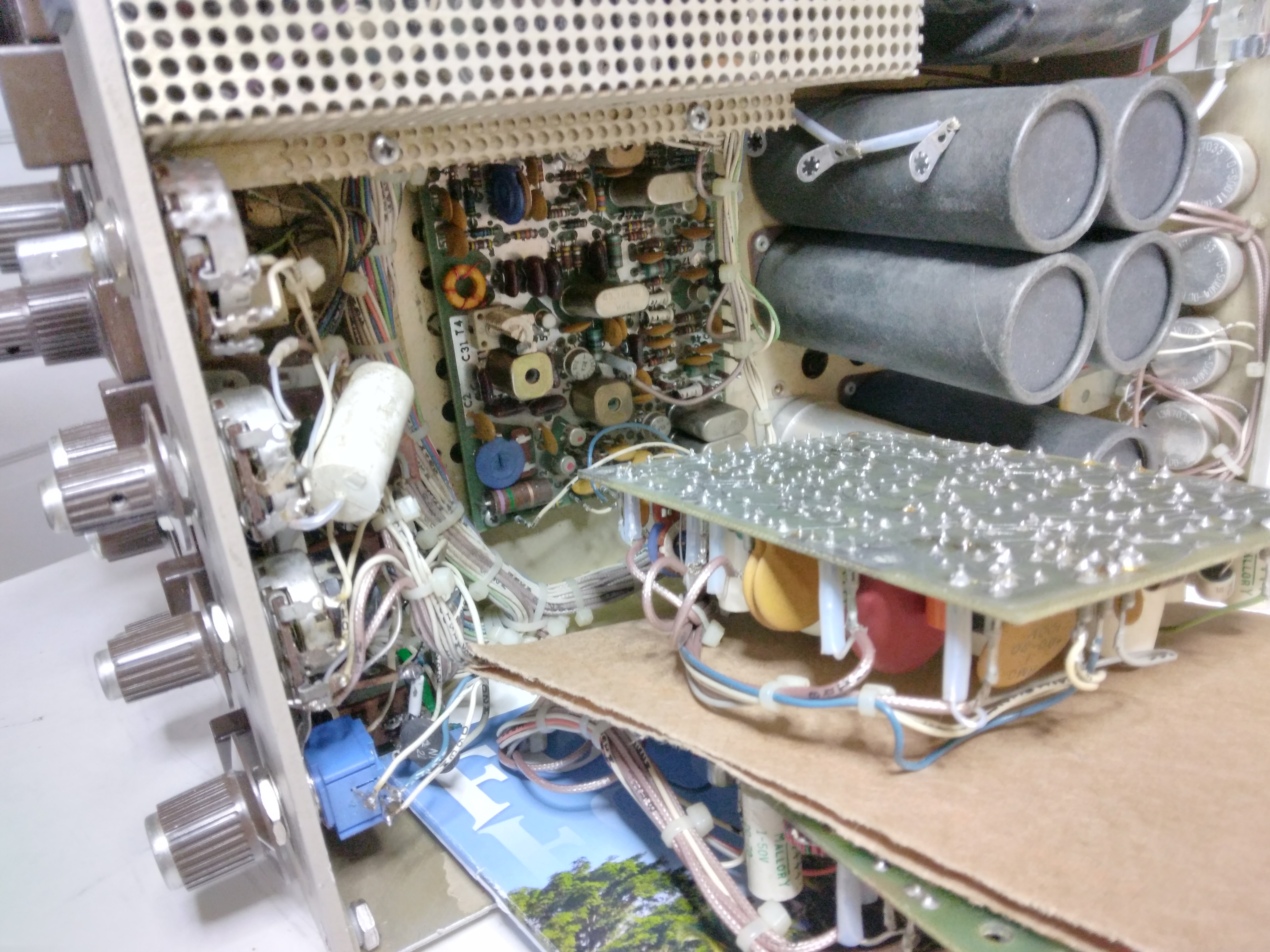
Now the problem is to actually get access to the board and specifically the trimmer R43. The board itself is beneath two other boards, and it also has a metal cover that needs to be removed. Below the two boards above the BFO board are repositioned and the cover of the BFO board at the bottom is removed.
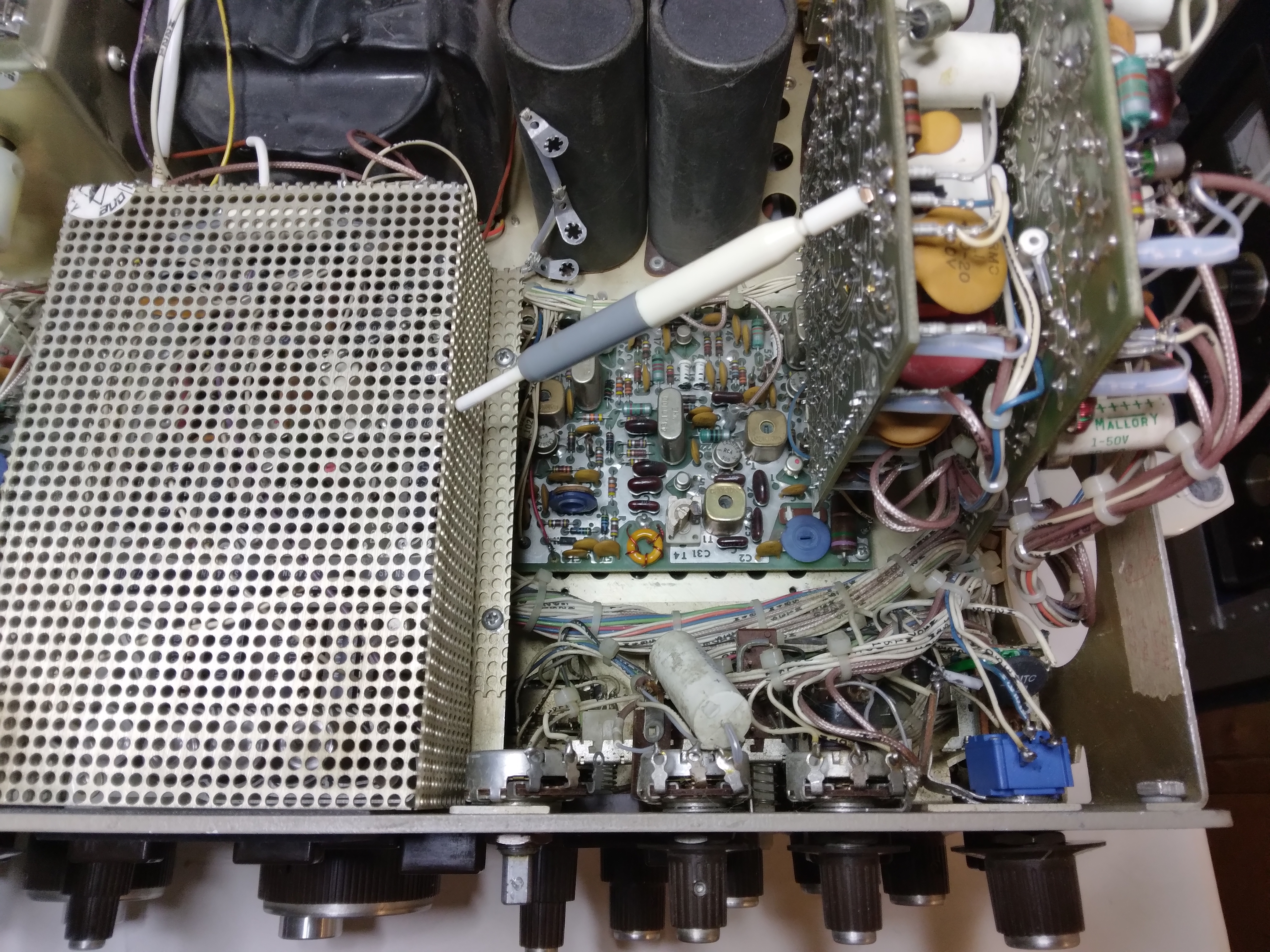
And while performing the offset adjustments on the BFO-board, below is how I use cardboard and a magazine to separate the boards and to make sure that they are not touching anything or shorthing to the chassie
Having access to both R43 and the trimmer coils I have now adjusted the offset so that a null coincides with the centre position of the TRANSMIT OFFSET knob on the front panel.
Update 2 October 2021
The AC switch
Now having a button on the AC switch feels good as the hole is filled on the front panel. However, the switch itself is not in good condition. It is clear that the previous owner has "worked" on it.
Below is the switch when opened up, you can see the pitted contacts of the switch and the warped board that holds the terminals.
I do not have a replacement so for the moment cleaning and rebuilding is the only option. Besides the pitted contacts the tabs holding the board to the metal frame are missing. They have snapped when the previous owner "worked" on the switch.
Here is the switch after I have cleaned it, reworked the contact points and lubricated the assembly, ready to go back into the radio.
The AC switch is now working well, no intermittent switching on/off and no sparks when operating the push button..!
The PA unit
One thing that I've come to realize while using the radio more extensively on different bands is that the PA TUNING is incorrect. As it turns out, the variable capacitor always ends up close to, or right at, minimum capacitance. This has not been obvious as the front panel PA TUNING knob indicator was offset and showed mid range when the capacitor was actually at minumum.
After looking at the schematic I decided that the only reason for this would be that the BROAD BAND switch in some way must have been compromised so that the BB capacitors are in parallell with the PA tuning, C1 at all times. To make sure how things should look inside the PA unit I opened up my own CX7 that is working as it should to do some comparisons. My CX7 is in the upper right hand corner and the CX7A under restoration is at the bottom of picture.
To make a long story short - the wafers on switch S1B (to the left of the coil in the picture below) that are supposed to switch between C1 manual PA TUNING and BROAD BAND were totally fried by RF and not making any contact at all. The wafer switch is beyond repair and needs to be replaced.
I then discovered that whoever worked on this radio before had soldered the wire from the BROAD BAND capacitor bank so that they were permanently parallelled to C1 !!
No wonder C1 needed to be at minimum on all bands. The solution for the moment is to completely de-activate broad band tuning and maintain manual tuning without any interaction from the fried wafer switch. In the picture below you can see the two wires from the BB capacitor assembly at the bottom of the PA unit, now fully disconnected and isolated with teflon tubing.
I do have a replacement wafer switch that I could use but to be able to perform the operation I need some very tiny Allen keys to undo the shaft extensions from C1 and the wafer switch that are going to the front panel. I do not have these at the moment.
Restoration process is coming to an end
This fine radio is now about to go back to it's owner Erik SM2CLY for further and hopefully daily use. It has been a fun project for me to restore the unit.
But the full restoration could not have been accomplished had it not been for the help and outstanding support from Fred K5OG. Not only has Fred sent me parts, he also maintains a website packed with information on these old Signal/One radios.
That's were I found the excellent material produced by Bob Sullivan W0YVA/4, especially his "SIGNAL ONE TROUBLE GUIDE". Invaluable to me in every aspect of the word.
Sharing information like this is essential for people like me to be able to work on boat anchor radios successfully - a big thank you to everyone involved!
Click on the small picture above to view a short video with some comments from me, of the fully restored CX7A in operation. The video quality is not good, it was a bit too dark in my shack when I made the recording, sorry about that.
73
Peter SM2CEW