
The pictures below show my 144 MHz EME amplifier using the QBL 5-3500.
The original two-part article that describes the anode stripline can be
found in December 1973 and January 1974 QST. The amplifier described in
that article uses an 8877 tube and is also featured in the ARRL Handbook
as "A 2kW PEP amplifier for 144 MHz". The input line and the screen bypass
shown here is designed specifically for the QBL tube. Specifications
for the QBL 5-3500 tube (PDF-format)
|
Anode 5000V @ 1.5A Heater 6.3V @ 32 A g1 -107V @ 40mA g2 +800V @ 80mA |
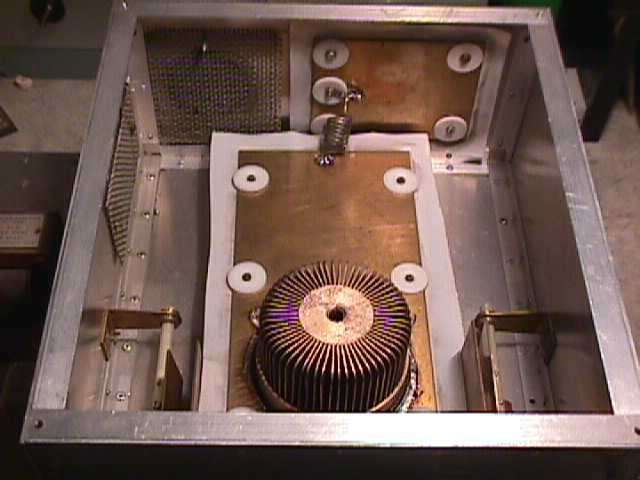
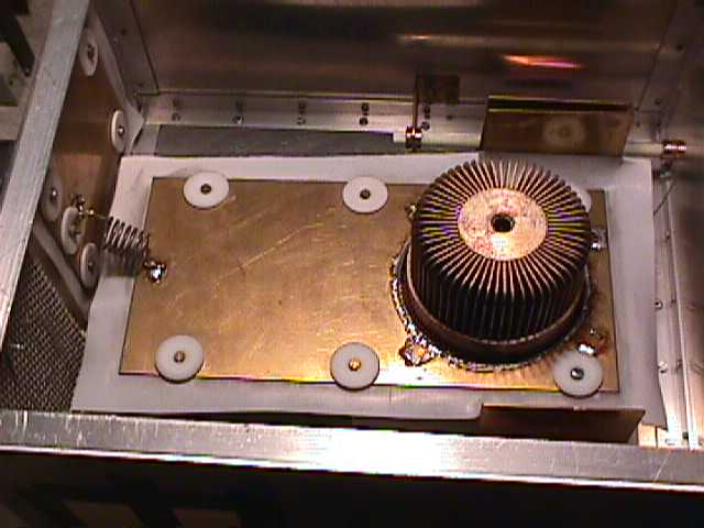
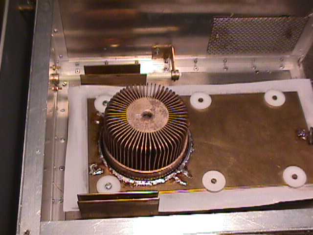
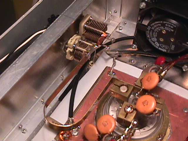
| Anode 1 | Anode side, stripline with flappers and bypass capacitor |
| Anode 2 | Anode different view, HV rfc to PTFE sandwich bypass capacitor |
| Anode 3 | Another view, flapper arrangement |
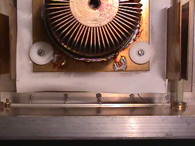
| Anode 4 | Anode, close view, neutralizing probe = 1mm dia wire, visible in the low right hand corner |
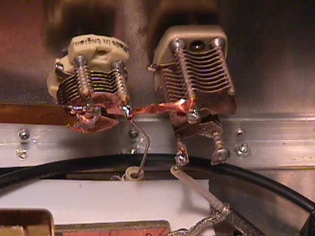
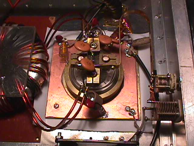
| Input 1 | Input circuit, stripline with serial butterfly capacitor plus capacitor to ground |
| Input 2 | Input capacitor, note the serial capacitor is butterfly with only stators connected on each side for very low series capacitance. Also note neutralizing probe, the 1 mm dia wire that protrudes into anode compartement. |
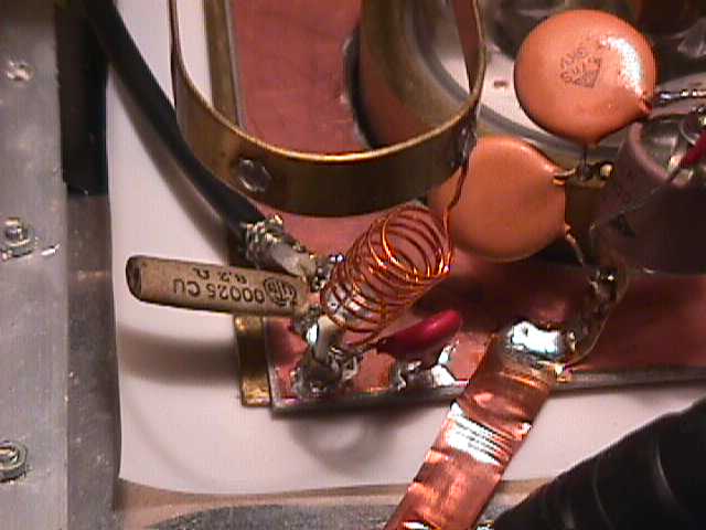
| Input 3 | Bias feed arrangement, RFC, serial resistora and bypass.Bias tap is on input line. |
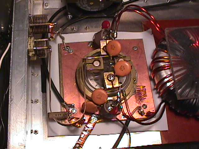
| Screen bypass 1 + input | Screen bypass, sandwich PTFE/brass capacitor with single side PC-board on top for added capacitance. |
| Screen bypass 2 + input | Another view. Also note filament transformer |
| Bottom view | Bottom view, filament transformer, output line, screen loading resistors |
| Front panel | Front panel of QBL 5-3500 amp for 144 MHz. All tuning, input/output accessable from front panel. |
| Driver amplifier | 4CX250B coaxial anode line amp |